
Message sending method and device

A technology for sending messages and devices, applied in the field of communications, and can solve problems such as lack of guarantee and transmission.

Active Publication Date: 2014-07-30
HUAWEI CLOUD COMPUTING TECH CO LTD
View PDF4 Cites 42 Cited by
  • Summary
  • Abstract
  • Description
  • Claims
  • Application Information

AI Technical Summary

Problems solved by technology

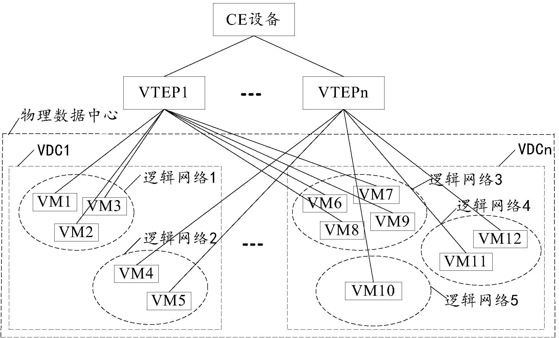
[0004] Because, in the prior art, in the process of realizing the above message transmission, for the source VMs in different VDCs in the same physical data center, the messages sent to the destination VMs across physical data centers are all sent through the same shared VPN tunnel transmission, the packets sent from the source VM located in a certain VDC to the destination VM across physical data centers cannot be transmitted through the VDC’s own dedicated VPN tunnel, resulting in the quality of service (Quality of Service, QOS) of the VDC ) is not guaranteed

Method used


Image

  • Message sending method and device
  • Message sending method and device
  • Message sending method and device

Examples


Embodiment 1

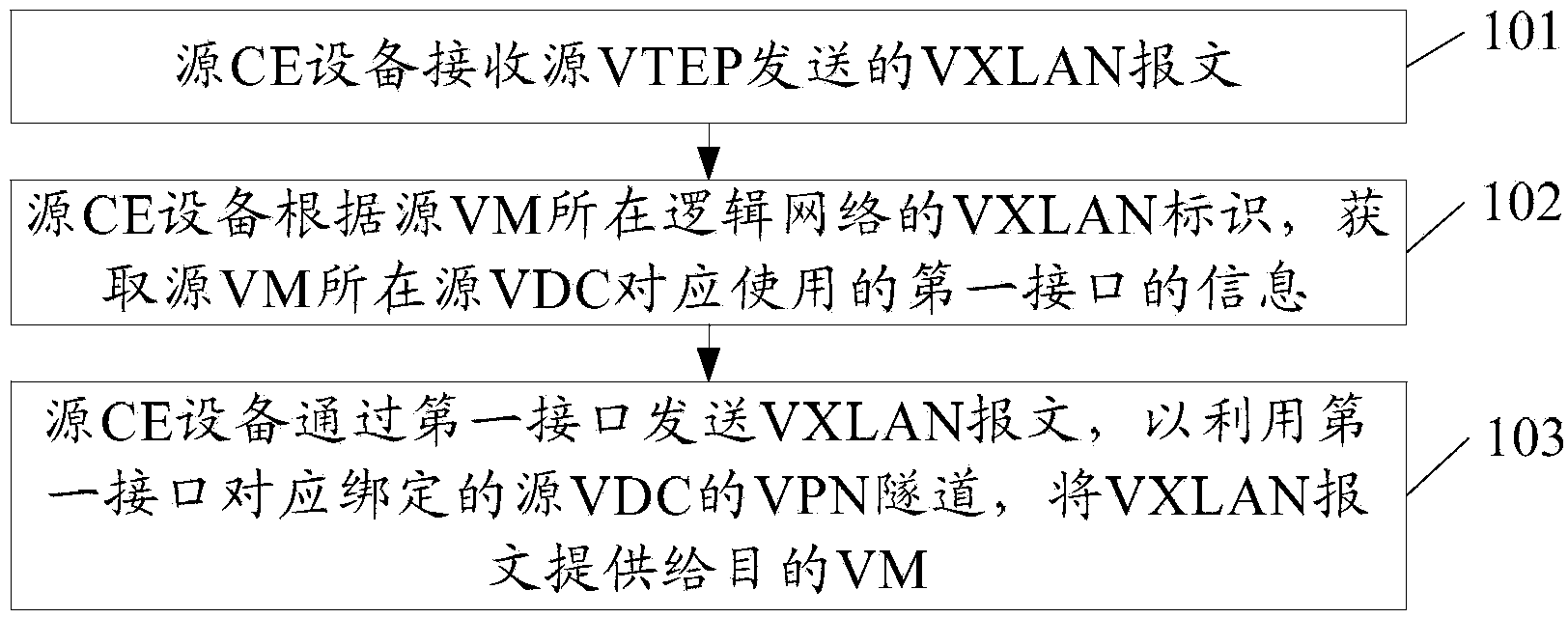
[0062] Embodiment 1 of the present invention provides a method for sending packets. A VPN tunnel is allocated to each VDC in the physical data center where the source VM is located in advance. The VPN tunnels allocated to each VDC in the physical data center where the source VM is located are different. The VPN tunnel assigned by the VDC in the physical data center where the source VM resides is bound to the interface of the source CE device corresponding to the VDC in the physical data center where the source VM resides. The first interface of the CE device corresponds to the binding. The first interface is the interface corresponding to the source VDC where the source VM resides. For example, figure 2 As shown, the method may include:

[0063] 101. The source CE device receives the VXLAN packet sent by the source VTEP.

[0064] Wherein, the VXLAN packet includes the original data packet that the source VM needs to send to the destination VM and the VXLAN identifier of the ...

Embodiment 2

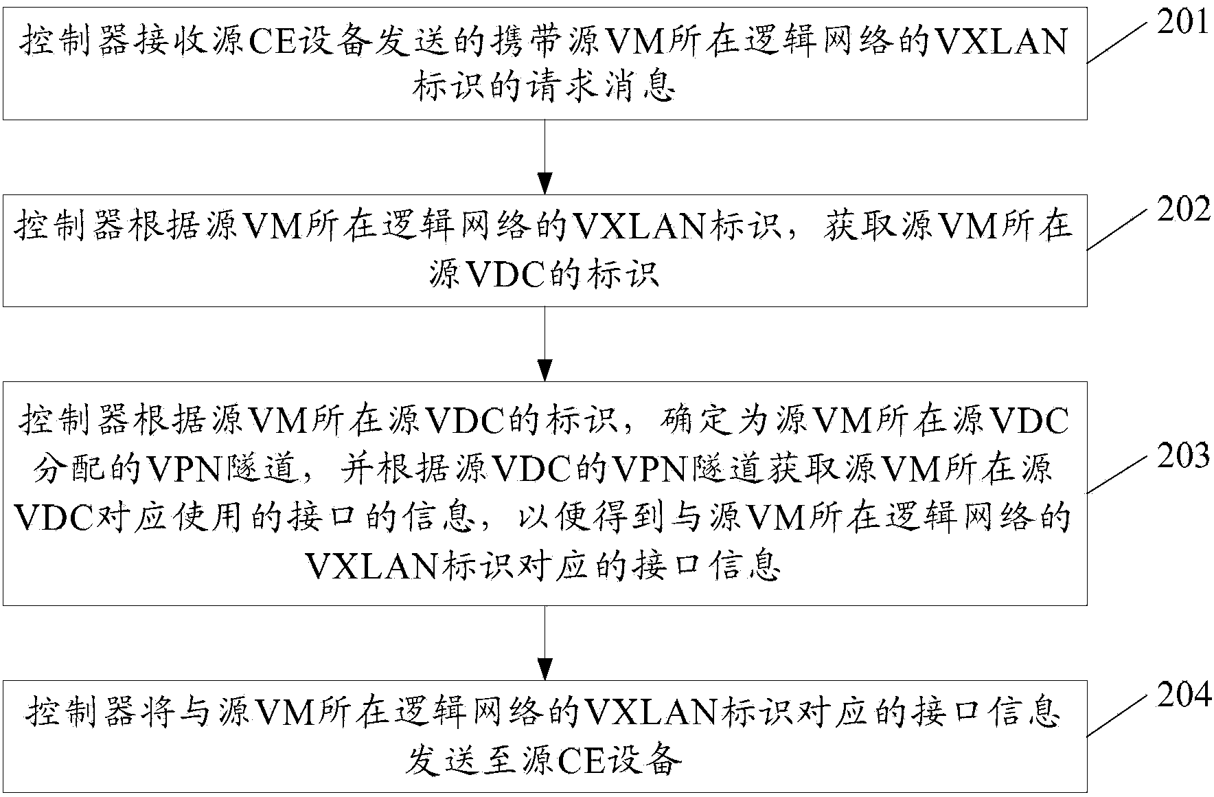
[0073] Embodiment 2 of the present invention provides a method for sending packets. A VPN tunnel is allocated to each VDC in the physical data center where the source VM is located in advance. The VPN tunnels allocated to each VDC in the physical data center where the source VM is located are different. The VPN tunnel assigned by the VDC in the physical data center where the source VM resides is bound to the interface of the source CE device corresponding to the VDC in the physical data center where the source VM resides. The first interface of the CE device corresponds to the binding. The first interface is the interface corresponding to the source VDC where the source VM resides. For example, image 3 As shown, the method may include:

[0074] 201. The controller receives a request message carrying the VXLAN identifier of the logical network where the source VM is sent from the source CE device.

[0075] Wherein, the request message is used to request to acquire the interfa...

Embodiment 3

[0085] Embodiment 3 of the present invention provides a method for sending packets. A VPN tunnel is allocated to each VDC in the physical data center where the source VM is located in advance. The VPN tunnels allocated to each VDC in the physical data center where the source VM is located are different. The VPN tunnel assigned by the VDC in the physical data center where the source VM resides is bound to the interface of the source CE device corresponding to the VDC in the physical data center where the source VM resides. The first interface of the CE device corresponds to the binding. The first interface is the interface corresponding to the source VDC where the source VM resides. For example, Figure 4 As shown, the method may include:

[0086] 301a. The source CE device receives the VXLAN packet sent by the source VTEP.

[0087] Wherein, the VXLAN packet includes the original data packet that the source VM needs to send to the destination VM and the VXLAN identifier of the...


PUM


Abstract

The invention discloses a message sending method and device and relates to the communication field. The message sending method and device solve the problem that due to the fact that a message located on a source VM of a certain VDC and sent to a target VM of a cross-physical data center cannot be transmitted through an exclusive VPN channel of the VDC, the QOS of the VDC cannot be guaranteed. According to the scheme, a source CE device receives a VXLAN message sent by a VTEP, wherein the VXLAN message contains an original data message to be sent to the target VM by the source VM and the VXLAN identification of a logic network where the source VM is located; the source CE device acquires the information of a first interface correspondingly used by the source VDC where the source VM is located according to the VXLAN identification of a logic network where the source VM is located; the source CE device sends the VXLAN message through the first interface to provide the VXLAN message for the target VM by utilizing the VPN channel of the source VDC correspondingly bound by the first interface. The message sending method and device are used for sending messages.

Description

technical field [0001] The invention relates to the communication field, in particular to a method and device for sending messages. Background technique [0002] In the data center network, different virtual local area networks (Virtual Local Area Networks, VLANs) need to be used to isolate the Layer 2 network data streams of different tenants. However, with the rapid development of communication technology, the number of VLANs can no longer satisfy more than 4000 tenants. Therefore, the industry has proposed a virtual extensible local area network (Virtual extensible Local Area Network, VXLAN) technology, which expands the segmented network identifier that only supports 12 bits in a VLAN to 24 bits, that is to say, from the maximum Support 4096 logical networks and expand to a maximum of 16000000 logical networks. [0003] In the existing VXLAN technology, a virtual data center (Virtual Data Center, VDC) can include multiple logical networks, each logical network correspon...

Claims


Application Information

Patent Timeline
IPC IPC(8): H04L12/725H04L12/827H04L47/265
Inventor 张辛波熊志强宋宇
Owner HUAWEI CLOUD COMPUTING TECH CO LTD
Learn More