
Imaging spectrometer

An imaging spectrometer and imaging technology, which is applied in the field of imaging spectrometer, can solve the problems of spectral line bending and band bending, which cannot satisfy the spectrometer, spectral order overlap, etc., and achieve large dispersion width, reduced volume and weight, and large field of view Effect

Inactive Publication Date: 2014-07-30
ACAD OF OPTO ELECTRONICS CHINESE ACAD OF SCI
View PDF4 Cites 12 Cited by
  • Summary
  • Abstract
  • Description
  • Claims
  • Application Information

AI Technical Summary

Problems solved by technology

Dispersive spectrometers usually use isosceles prisms or compound prisms, which will cause large spectral line bending and band bending, which will have a certain impact on later data processing. For large field systems, the spectral line bending is very large, and the system will be larger
The grating spectrometer is limited by the diffraction efficiency, the energy of the system entering the detector is less, the signal-to-noise ratio of the system is low, and the spectral order overlaps, and there are many ghost images.
[0003] Therefore, the above two conventional dispersion schemes cannot meet the spectrometer's large field of view, miniaturization, and lightweight development requirements

Method used


Image

  • Imaging spectrometer
  • Imaging spectrometer
  • Imaging spectrometer

Examples


Embodiment Construction

[0017] The technical solutions in the embodiments of the present invention will be clearly and completely described below in conjunction with the accompanying drawings in the embodiments of the present invention. Obviously, the described embodiments are only some of the embodiments of the present invention, not all of them. Based on the embodiments of the present invention, all other embodiments obtained by persons of ordinary skill in the art without making creative efforts belong to the protection scope of the present invention.

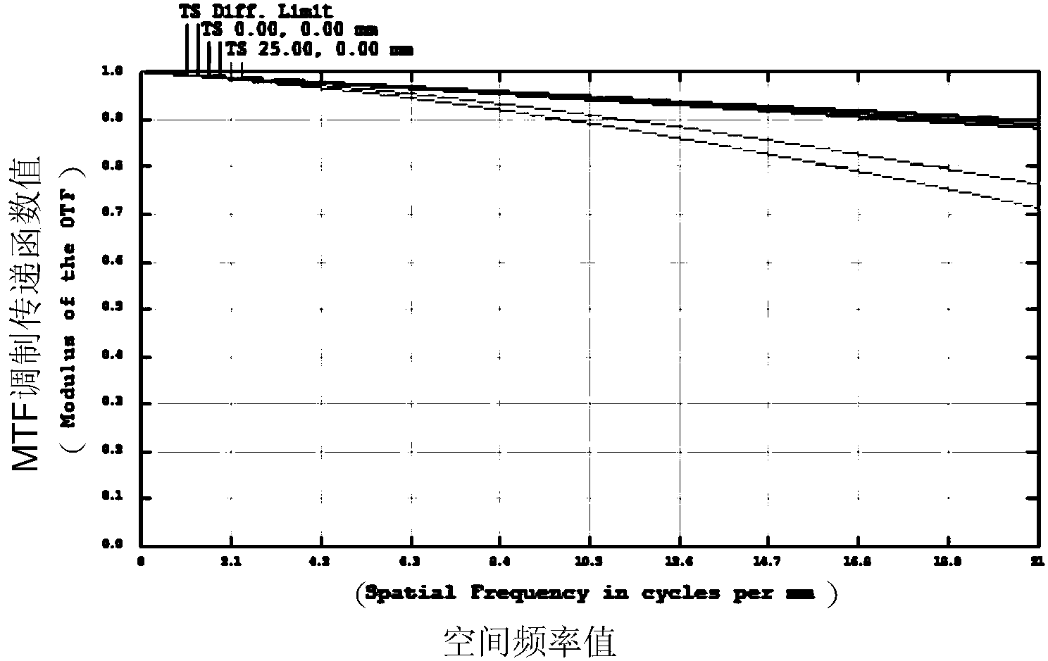
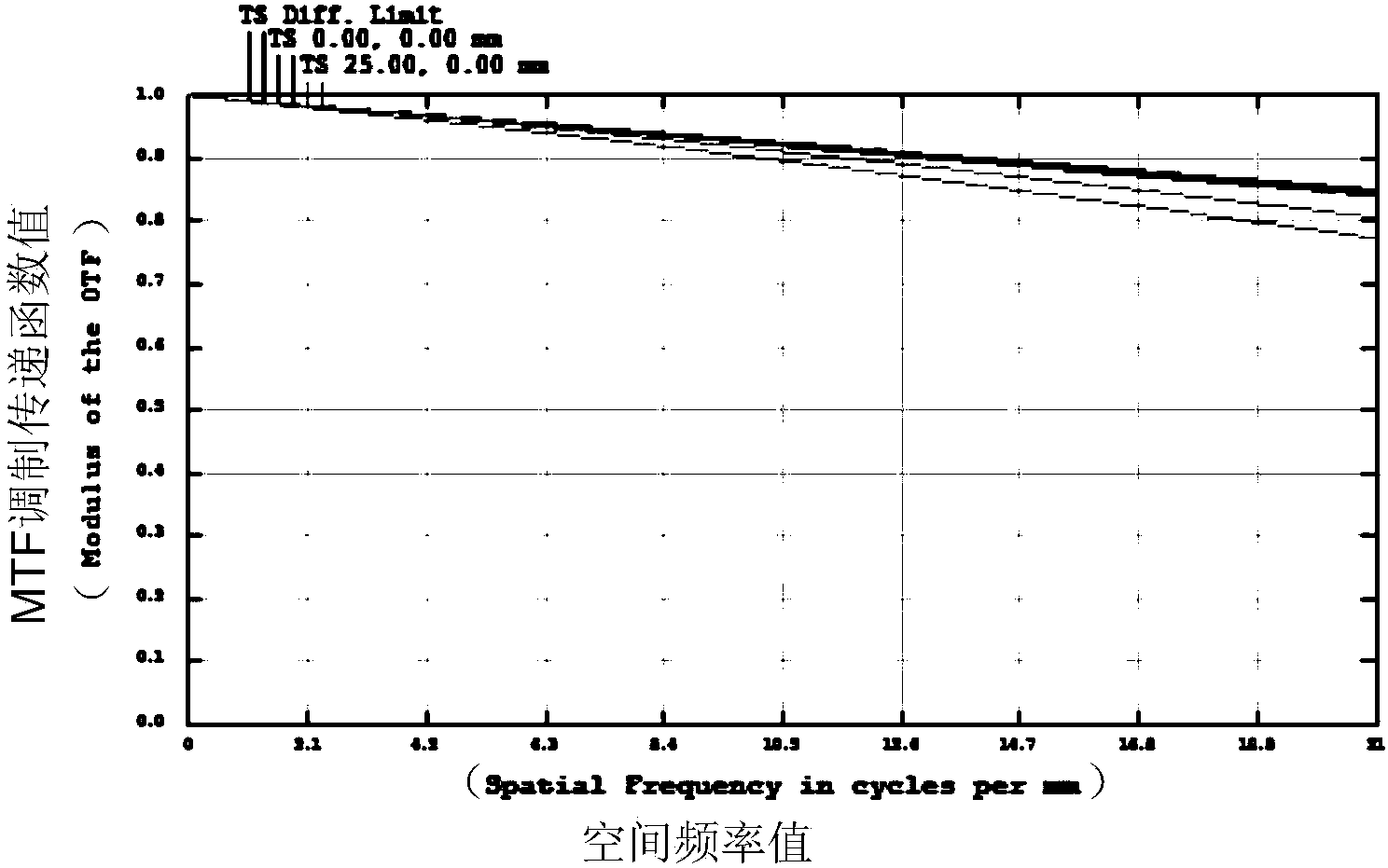
[0018] Such as figure 1 As shown, the embodiment of the present invention provides an imaging spectrometer, including a first Fery prism 11, a first primary reflector 12, a secondary reflector 13, a second Fery prism 14, and a second primary reflector 15:

[0019] The light that enters through the slit 10 is transmitted through the first Fery prism 11 and reaches the first main reflector 12, after being reflected by the first main reflector 12, it ...


PUM

PropertyMeasurementUnit
Lengthaaaaaaaaaa

Abstract

The invention discloses an imaging spectrometer. The imaging spectrometer comprises a first Fery prism, a first main reflector, a subsidiary reflector, a second Fery prism and a second main reflector. Light entering the imaging spectrometer through a slit arrives at the first main reflector after being transmitted by the first Fery prism, reaches the first Fery prism after being reflected by the first main reflector, reaches the subsidiary reflector after being transmitted by the first Fery prism, arrives at the second Fery prism after being reflected by the subsidiary reflector, reaches the second main reflector after being transmitted by the second Fery prism, arrives at the second Fery prism after being reflected by the second main reflector, and arrives at an imaging plane to realizing imaging after being transmitted by the second Fery prism. According to the imaging spectrometer, the light passes through the same Fery prism twice for chromatic dispersion, so that the size and weight of a system are reduced, a large view field is obtained, and a quite large chromatic dispersion width is obtained.

Description

technical field [0001] The invention relates to the technical field of spectral imaging, in particular to an imaging spectrometer. Background technique [0002] Dispersion imaging spectrometers include prism dispersion and grating dispersion. Among them, the prism dispersion type mainly uses the different refractive indices of the light of different wavelengths passing through the prism, so that the light of different wavelengths is dispersed at different angles. The grating dispersion type mainly uses a grating as a dispersion element, and the grating is a component formed by a series of notches carved on a high-precision plane or curved surface. Dispersive spectrometers usually use isosceles prisms or compound prisms, which will cause large spectral line bending and band bending, which will have a certain impact on later data processing. For large field systems, the spectral line bending is very large, and the system The volume will be larger. The grating spectrometer i...

Claims


Application Information

Patent Timeline
IPC IPC(8): G01J3/28
Inventor 冯蕾周锦松付锡禄何晓英张雪静李亚灿刘盺悦卜美霞
Owner ACAD OF OPTO ELECTRONICS CHINESE ACAD OF SCI
Learn More