Hydraulic energy conversion system mounted inside tire

A technology for converting system and hydraulic energy, applied in the direction of mechanical power generating mechanism, machine/engine, mechanical equipment, etc., can solve the problems of waste and conversion, and achieve the effect of high conversion rate

Inactive Publication Date: 2014-07-30
冯柯霖
View PDF4 Cites 2 Cited by
  • Summary
  • Abstract
  • Description
  • Claims
  • Application Information

AI Technical Summary

Problems solved by technology

[0003] But the function of existing wheels and tires is only as the function of keeping its safe and smooth running when the car is running, and the energy that the tires have when the car is running has not been converted in time into the energy required by the car or the energy we need. Effective energy; the energy of the wheels and tires of the prior art will be wasted in vain

Method used


Image

  • Hydraulic energy conversion system mounted inside tire
  • Hydraulic energy conversion system mounted inside tire
  • Hydraulic energy conversion system mounted inside tire

Examples


Embodiment 1

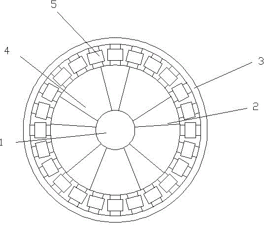
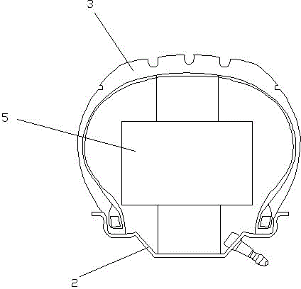
[0019] A hydraulic energy conversion system installed in the tire described in Embodiment 1, such as figure 1 , figure 2 As shown, it includes a wheel 1 used in conjunction with the main frame of the automobile. The wheel is composed of a rim 2 installed and connected to the axle, a tire 3 installed with the rim, and spokes 4 provided on the rim. A plurality of ring-shaped hydraulic systems 5 arranged on the ground; the hydraulic system is connected to the generator set on the wheel rim or the main frame of the car through the crankshaft linkage mechanism and transmits power to the generator for power generation; the hydraulic system is a hydraulic cylinder, A return spring is provided on the hydraulic cylinder for resetting the reciprocating motion of the hydraulic cylinder. This technical solution directly installs multiple hydraulic systems in the tires. The hydraulic system receives the extrusion of the ground and uses the force of the vehicle's own weight and driving fo...

Embodiment 2

[0025] This embodiment 2 is improved on the basis of embodiment 1, and the specific difference of this embodiment 2 is:

[0026] The generator is directly installed and hidden in the main frame of the automobile. The generator can also be hidden in the main frame of the car and integrated with the main frame of the car to solve the installation position and complexity of the wheels.

Embodiment 3

[0028] This embodiment 3 is improved on the basis of embodiment 1, and the specific difference of this embodiment 2 is:

[0029] Such as Figure 5 , Image 6 As shown, the tire adopts a double-layer tire structure, specifically: the surface of the tire 3 is covered with a layer of elastic tire 33 to form a double-layer tire, and the hydraulic system 5 is located between the tire surface and the back of the elastic tire.


PUM


Abstract

The invention discloses a hydraulic energy conversion system mounted inside a tire. The system comprises a vehicle wheel matched with a vehicle main frame, wherein the vehicle wheel consists of a rim connected with an axle, the tire mounted on the rim and spokes arranged on the rim; a plurality of annular hydraulic systems facing toward ground are arranged inside the cavity of the tire; each hydraulic system is connected with the rim or a generator on the vehicle main frame through a crankshaft connecting rod system, and transfers power to the generator for generating electricity; the hydraulic systems are hydraulic cylinders, and return springs are arranged on the hydraulic cylinders for the reset of hydraulic cylinder reciprocating motion. The hydraulic energy conversion system mounted inside the tire mainly utilizes the self-weight of a vehicle and the acting force on the tire during the driving of the vehicle, and converts the acting force into a mechanical energy for generating electricity; extrusion force is directly applied to the hydraulic systems from the ground, so as to enable power pieces of the hydraulic systems to output reciprocating power, and transfer the reciprocating power to the generator for generating electricity.

Description

technical field [0001] The present invention relates to the technical field of generating reciprocating compression power for power generation by means of automobile driving, and in particular to a method for converting mechanical energy into electrical energy by utilizing the gravity of the automobile itself and driving power, and utilizing the reciprocating compression power device installed in the automobile tire. Hydraulic energy conversion system. Background technique [0002] Tires are one of the important parts of the car. They are in direct contact with the road surface, and work together with the car suspension to ease the impact of the car while driving, ensuring that the car has good seating comfort and smooth driving; ensuring that the wheels and the road are in good condition The adhesion of the tire improves the traction, braking and passability of the car; bearing the weight of the car, the important role played by the tire on the car has attracted more and mo...

Claims


Application Information

Patent Timeline
IPC IPC(8): F03G7/00
Inventor 冯柯霖
Owner 冯柯霖
Why Eureka
Try Eureka