Tensioner with air brake function

A technology of tensioner and function, applied in the field of tensioner with airflow brake function, can solve the problems of time-consuming and labor-intensive

Active Publication Date: 2016-01-20
WUJIANG KESHIDA TEXTILE
View PDF7 Cites 0 Cited by
  • Summary
  • Abstract
  • Description
  • Claims
  • Application Information

AI Technical Summary

Problems solved by technology

When the two-for-one twister stops running, the ordinary yarn tensioner cannot brake the yarn through soft holding, and can only be processed by cutting the yarn. This way makes the machine restart one by one Bit structure, time-consuming and labor-intensive

Method used


Image

  • Tensioner with air brake function
  • Tensioner with air brake function
  • Tensioner with air brake function

Examples


Embodiment Construction

[0018] The present invention will now be further described in detail in conjunction with the accompanying drawings and embodiments. These drawings are all simplified schematic diagrams, only illustrating the basic structure of the present invention in a schematic manner, so it only shows the composition related to the present invention.

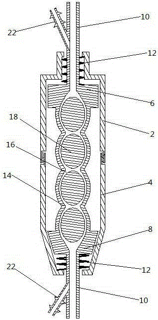
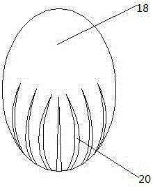
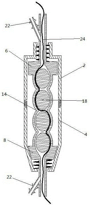
[0019] Such as figure 1 with figure 2 As shown, a tensioner with an airflow brake function includes an upper cover 2 and a lower cover 4 interconnected with internal and external threads, the upper cover 2 and the lower cover 4 are cylindrical, and the lower end of the upper cover 2 and the lower The opening threads on the upper end of the cover 4 are connected to each other. The upper end of the upper cover 2 and the lower end of the lower cover 4 are respectively provided with small openings. Pass through the small opening at the lower end of the lower cover 4, the yarn tube 10 is a hollow tube structure, the yarn 24 can smoothly pass thr...


PUM


Abstract

The invention relates to a tensioner with an air flow brake function. The tensioner comprises a drum-shaped upper cover and a drum-shaped lower cover which are connected together by threads; an upper support and a lower support respectively penetrate the interiors of the upper cover and lower cover in a sleeving mode; a ball bag is hermetically connected between the upper support and the lower support; the ball bag is provided with at least one bag cavity along the axial direction of the tensioner; each two adjacent bag cavities are communicated by a yarn path; each bag cavity is oval ball-shaped; tension oval balls are arranged in the bag cavities; an air leaking slot is arranged at the surface of the lower part of each tension oval ball; the other surface of each tension oval ball is smooth. The multiple tension oval balls are placed in the ball bag, yarns are held by the inner wall of the ball bag and the surfaces of the tension oval balls, and stable tension control can be generated for the yarns after the folding forces for the yarns from the multiple oval bags are overlapped; the air leaking slots are arranged at the corresponding ends of the tension oval balls, so the brake holding or penetrating yarn releasing control of the tension oval balls on the yarns can be adjusted according to the air flow direction.

Description

technical field [0001] The invention relates to a yarn tension controller, in particular to a tensioner with airflow braking function. Background technique [0002] A two-for-one twister is a spinning device that twists two or more strands of yarn into one yarn after high-efficiency twisting. Before the yarn enters the twisting area for twisting, it is necessary to control the yarn entering the twisting area If the entering speed is too fast, the yarn will be wound on the twisting spindle, causing yarn breakage and spindle winding. If the entering speed is too slow, it will directly cause yarn breakage. A certain tension is generated, and the yarn tensioner is a special device that can control the tension of the yarn at this time. When the two-for-one twister stops running, the ordinary yarn tensioner cannot brake the yarn through soft gripping, and can only be processed by cutting the yarn. This way makes the machine restart one by one Bit structure, time-consuming and la...

Claims


Application Information

Patent Timeline
Patent Type & Authority Patents(China)
IPC IPC(8): D01H13/10
Inventor 庄郁峰
Owner WUJIANG KESHIDA TEXTILE
Why Eureka
Try Eureka