


Quick Research
Generate reliable direction feasibility study reports for your R&D in just a few steps.

Technical Q&A
Discover and master advanced knowledge NOW. Basics, ideas, possibilities, all at once.

Find Solutions
As an expert in R&D theories, this can generate solutions to your technical problems instantly.

Evaluate Feasibility
Analyze your overall solution with one click, know your potential R&D risks in advance.

Monitor Landscape
Get weekly tech updates, stay abreast of the latest tech innovations and key insights.
Control information sending method, control information receiving method, and related devices
A technology for controlling information and sending method, which is applied in error prevention/detection using return channel, digital transmission system, electrical components, etc. It can solve problems such as inability to transmit control information normally, and achieve the effect of reducing complexity and improving transmission efficiency.
- Summary
- Abstract
- Description
- Claims
- Application Information
AI Technical Summary
Problems solved by technology
Method used
Image

Examples
Embodiment 1
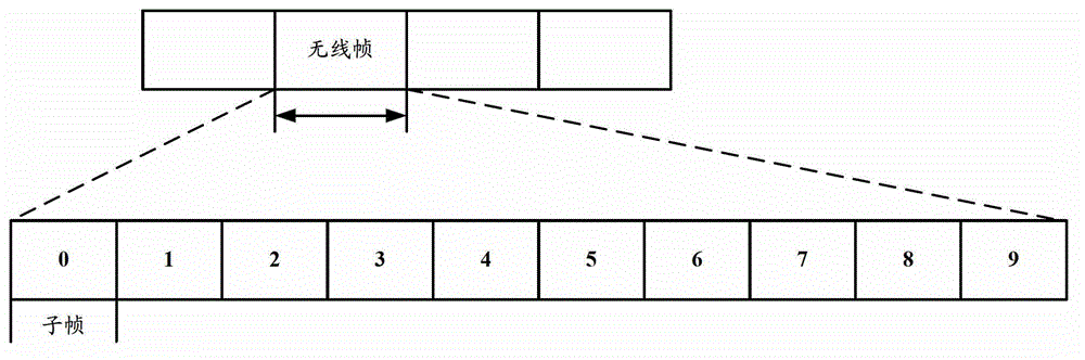
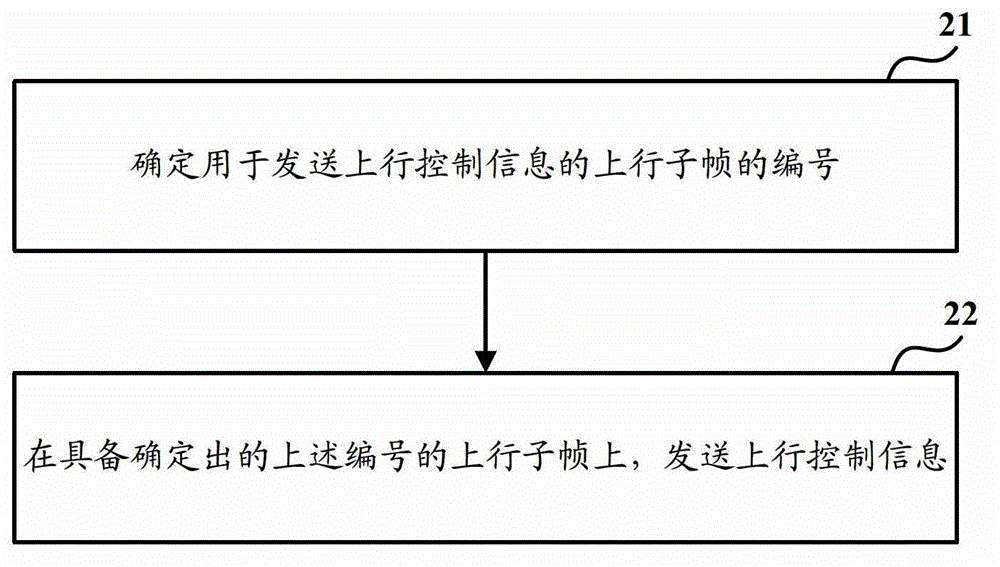
[0049] Such as figure 2 As shown, it is a main flow chart of a method for sending uplink control information provided by an embodiment of the present invention. The execution subject of this method may be the terminal side, and it is applied in a dynamic TDD mode using a specified set of uplink and downlink subframe configuration methods. , the method includes the following steps:
[0050] Step 21, determining the number of the uplink subframe used to send the uplink control information;
[0051] Wherein, the number is: a number among numbers of subframes configured as uplink subframes in the specified set of uplink and downlink subframe configuration modes. Specifically, the subframes configured as uplink subframes in the set of uplink and downlink subframe configuration modes refer to: all configured as uplink subframes in the various configuration modes of uplink and downlink subframes included in the set of uplink and downlink subframe configuration modes. The subframe ...
Embodiment 2
[0084] Such as Figure 6 As shown, it is a main flow chart of a method for sending downlink control information provided by the embodiment of the present invention. The execution body of the method may be the network side, and it is applied in the dynamic TDD mode using the specified set of uplink and downlink subframe configuration methods. , the method includes the following steps:
[0085] Step 61, determining the number of the downlink subframe or special subframe used to send the downlink control information;
[0086]Wherein, the number of the downlink subframe or special subframe used to send downlink control information is: one of the numbers of subframes configured as downlink subframes or special subframes in the specified set of uplink and downlink subframe configuration modes Numbering. Specifically, the subframes configured as uplink subframes in the set of uplink and downlink subframe configuration modes refer to: all configured as downlink subframes in the vari...
PUM
 Abstract
Description
Claims
Application Information
 - R&D Engineer
- R&D Manager
- IP Professional
- Industry Leading Data Capabilities
- Powerful AI technology
- Patent DNA Extraction
Browse by: Latest US Patents, China's latest patents, Technical Efficacy Thesaurus, Application Domain, Technology Topic, Popular Technical Reports.
© 2024 PatSnap. All rights reserved.Legal|Privacy policy|Modern Slavery Act Transparency Statement|Sitemap|About US| Contact US: help@patsnap.com