Rotor having arc cutting structure

A rotor and arc-cutting technology, applied in the field of rotors, can solve problems such as difficult manufacture, smaller drive torque, and reduced change rate of equivalent reluctance of the magnetic circuit, so as to increase the strength of the mechanical structure, reduce torque ripple, and improve The effect of back EMF

Inactive Publication Date: 2014-07-23
TECO ELECTRIC AND MACHINERY
View PDF6 Cites 2 Cited by
  • Summary
  • Abstract
  • Description
  • Claims
  • Application Information

AI Technical Summary

Problems solved by technology

However, if the air gap equivalent magnetic flux is reduced due to the reduction of cogging torque, the driving torque will be reduced at the same time, so this method is rarely used; the other is to reduce the change rate of the magnetic circuit equivalent reluctance relative to the rotation angle , which is mainly the cog structure on the armature core to accommodate the winding. When it rotates relative to the pole core, the magnetic flux path changes, resulting in a relative change in the equivalent reluctance of the magnetic circuit, resulting in cogging torque
[0005] However, in the existing methods of suppressing the cogging torque, such as reducing the change of the total equivalent reluctance around the air gap, it is easy to increase the cost and time schedule of manufacturing, assembly and inspection; Although the design of grooves or oblique magnetic poles can suppress vibration and noise, in the process of practical production, it is often difficult to make winding and production. Therefore, the existing rotors that can reduce torque ripple still have room for improvement

Method used


Image

  • Rotor having arc cutting structure
  • Rotor having arc cutting structure
  • Rotor having arc cutting structure

Examples


Embodiment Construction

[0048] In the rotor provided by the present invention, there are too many combination implementations, so it is not repeated here one by one, and only one preferred embodiment is listed for specific description.

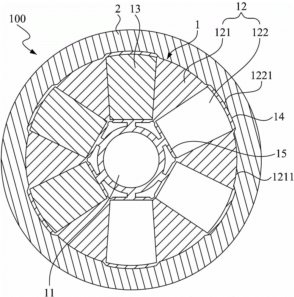
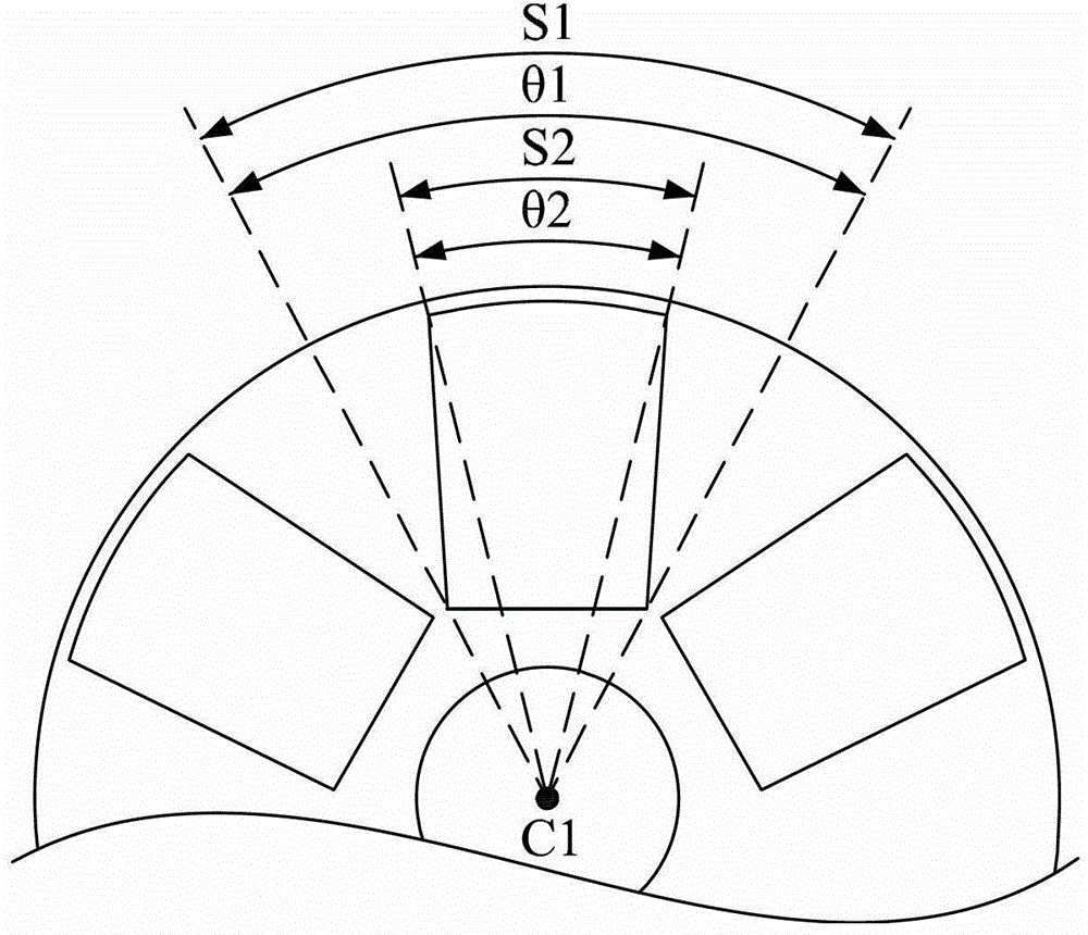
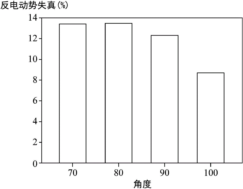
[0049] Please also refer to Figure 1 to Figure 3B , figure 1 A schematic diagram of a rotor with a cut arc structure showing a preferred embodiment of the present invention, figure 2 A schematic diagram of a fan-shaped magnet showing a preferred embodiment of the present invention, Figure 2A A schematic diagram showing the back EMF distortion simulation of the fan-shaped magnet design of the preferred embodiment of the present invention, Figure 2B A schematic diagram showing the torque ripple simulation of the sector magnet design of the preferred embodiment of the present invention, image 3 A schematic diagram showing a first circular arc and a second circular arc of a preferred embodiment of the present invention, Figure 3A A schematic diagram showing the...


PUM


Abstract

The invention relates to a rotor having an arc cutting structure. The rotor is used for being arranged in a stator of a motor, and comprises a rotating shaft, a rotor core and a plurality of sector-shaped magnets. The rotor core comprises a plurality of iron core parts and a plurality of magnet accommodating grooves, the iron core parts are mutually connected and integrally formed, and have a first circular arc, and the first circular arc corresponds to a first centre of curvature. The magnet accommodating grooves are sector-shaped, arranged among the iron cores parts, and correspond to a second circular arc, the second circular arc is connected to the first circular arc, and corresponds to a second centre of curvature, and the second centre of curvature is different from the first centre of curvature. The sector-shaped magnets are correspondingly accommodated in the magnet accommodating grooves.

Description

technical field [0001] The invention relates to a rotor with an arc-cutting structure, in particular to a rotor whose iron core has iron core portions corresponding to different circular arcs and magnet accommodating grooves, and the magnets are fan-shaped. Background technique [0002] Generally speaking, whether it is industrial applications, transportation, or household appliances, etc., rotating electrical machines (including motors and generators) are often used as the source of kinetic energy to convert electrical energy into mechanical energy, and then the generated mechanical energy is further processed. application. Motors are divided into permanent magnet brushless motors and wound field excitation motors. Compared with wound field excitation motors, the rotor of permanent magnet brushless motors contains permanent magnets, which can save the use of carbon brushes and slip rings. Therefore, With the advantages of high efficiency, high power density, high durabilit...

Claims


Application Information

Patent Timeline
Patent Type & Authority Applications(China)
IPC IPC(8): H02K1/27
Inventor 洪联馨谢培升黄庆智
Owner TECO ELECTRIC AND MACHINERY
Why Eureka
Try Eureka