
Automobile tail gas detection system based on RFID (Radio Frequency Identification)

A technology of automobile exhaust and detection system, which is applied in the direction of measuring devices, instruments, scientific instruments, etc., can solve the problems of inconvenient testing and inability to truly reflect exhaust emissions, and achieve good application prospects and save detection time.

Inactive Publication Date: 2014-07-23
李雅帝
View PDF0 Cites 10 Cited by
  • Summary
  • Abstract
  • Description
  • Claims
  • Application Information

AI Technical Summary

Problems solved by technology

[0003] The purpose of the present invention is to overcome the problem that the traditional automobile exhaust detection method adopts the chassis dynamometer test method, which must be completed indoors, cannot truly reflect the exhaust emissions on the actual road, and the test is inconvenient

Method used


Image

  • Automobile tail gas detection system based on RFID (Radio Frequency Identification)

Examples


Embodiment Construction

[0010] The present invention will be further described below in conjunction with the accompanying drawings. The following examples are only used to illustrate the technical solution of the present invention more clearly, but not to limit the protection scope of the present invention.

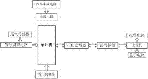
[0011] Such as figure 1 As shown, the RFID-based vehicle exhaust detection system includes a detection unit and a host computer. The detection unit is installed on the chassis of the vehicle. The detection unit includes an exhaust sensor, a signal conditioning circuit, a single-chip microcomputer and an RFID reader. At the trachea, the exhaust gas sensor is connected to the single-chip microcomputer through the signal conditioning circuit, and the single-chip microcomputer communicates wirelessly with the upper computer through the RFID reader-writer. The upper computer is used to receive the read-write tags sent by the RFID reader-writer. Alarm circuit, display circuit, and exhaust sensors inc...


PUM


Abstract

The invention discloses an automobile tail gas detection system based on RFID (Radio Frequency Identification). The automobile tail gas detection system comprises a detection unit and an upper computer, wherein the detection unit is mounted on an automobile chassis; the detection unit comprises a tail gas sensor, a signal conditioning circuit, a single chip microcomputer and an RFID reader-writer; the tail gas sensor is mounted on an automobile tail gas pipe; the tail gas sensor is connected with the single chip microcomputer by the signal conditioning circuit; the single chip microcomputer is in wireless communication with the upper computer by the RFID reader-writer and can be used for detecting tail gas components when an automobile runs on an actual rod and immediately judging whether automobile tail gas exceeds the standard or not according to a detection result; the detection time is reduced effectively and the application prospect is good.

Description

technical field [0001] The invention relates to an RFID-based automobile exhaust detection system, which belongs to the technical field of electronic measurement. Background technique [0002] The traditional vehicle exhaust detection method adopts the chassis dynamometer test method. The working principle of this method is: in the room, combined with the chassis dynamometer and the gas analyzer, the exhaust emission of the motor vehicle is tested under the preset driving conditions of the motor vehicle. . However, since this method must be carried out indoors and requires testing of motor vehicles according to fixed driving conditions, it cannot truly reflect the exhaust emissions on the actual road, and the emission test system is too large in size and difficult to operate during use. It often takes a lot of time to get the test results. Contents of the invention [0003] The purpose of the present invention is to overcome the problem that the traditional automobile e...

Claims


Application Information

Patent Timeline
Patent Type & Authority Applications(China)
IPC IPC(8): G01N33/00
Inventor 李雅帝
Owner 李雅帝
Learn More