Real vehicle collision test system of rail vehicles

A test system and technology for rail vehicles, applied in the field of rail vehicle collision test systems, can solve the problems of high energy level, large collision area and large volume during collision, and achieve the effect of simple and easy operation, scientific and reasonable structure

Active Publication Date: 2014-07-23
CENT SOUTH UNIV
View PDF7 Cites 21 Cited by
  • Summary
  • Abstract
  • Description
  • Claims
  • Application Information

AI Technical Summary

Problems solved by technology

[0005] The two technical solutions disclosed above, although they can be applied in the automotive field, they cannot be directly used in the impact test of rail vehicles.
The fundamental reason is the particularity of the structure of rail vehicles, which are large in size, mass, and large in impact area, generally not less than 4 meters by 4 meters; especially rail vehicles running on high-speed rails have high speeds and high energy levels during impact, so they cannot For direct reference, it is necessary to redevelop the real vehicle crash test system for rail vehicles

Method used


Image

  • Real vehicle collision test system of rail vehicles
  • Real vehicle collision test system of rail vehicles

Examples


Embodiment 1

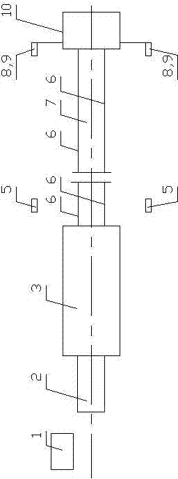
[0052] The real car 3 and the simulated car 10 are placed on the same rail 6 installed on the foundation 7; the transmitter 2 is installed at the end of the real car 3 facing away from the simulated car 10; the quality of the simulated car 10 can be adjusted as required; the simulated car 10 The end facing the actual vehicle 3 is sequentially installed with a uniform force plate 11 and a load cell array 12 from the outside to the inside; the simulation vehicle 10 is installed on one side or both sides of the end facing the actual vehicle 3, and the impact speed measuring device 8 and the high-speed photography device 9 are installed on the cantilever , the vertical line of the impact speed measuring device 8 and the high-speed photography device 9 is located in the plane formed by the end face of the simulated vehicle 10 facing the real vehicle 3; the electronic control part of the central console 1 and the transmitter 2, the impact speed measuring device 8, the The force-measu...

Embodiment 2

[0054] On the basis of Embodiment 1, another transmitter 2 connected to the central console 1 is configured for the simulated vehicle 10; during the impact test, the two transmitters 2 work simultaneously, respectively pushing the real vehicle 3 and the simulated vehicle 10 towards each other or Glide in the same direction until they collide. Able to conduct collision or rear-end collision tests.

Embodiment 3、4

[0056] On the basis of Embodiments 1 and 2 respectively, both the real vehicle 3 and the simulated vehicle 10 are equipped with a speed-regulating braking device connector 4 used in the commissioning condition, and the braking device connector 4 can be connected to the braking device; Two sets of debugging speed measuring devices 5 are installed on one side or both sides. The vertical lines of one set of debugging speed measuring devices 5 are located at the position where the actual vehicle 3 starts to slide freely, and the other set of debugging speed measuring devices 5 are located at the same position. The position where the simulated car 10 starts to slide freely; but the real car 3 and the simulated car 10 cannot be connected to the braking device at the same time.


PUM


Abstract

A real vehicle collision test system of rail vehicles comprises a central control platform, a transmitter, a real vehicle and a simulation vehicle; special software is arranged on the central control platform; the real vehicle and the simulation vehicle are placed on the same steel rail; one end of the real vehicle, which is back to the simulation vehicle, is provided with the transmitter; a uniform force plate and a force measurement sensor array are arranged at one end of the simulation vehicle from outside to inside in turn, wherein the end of the simulation vehicle faces to the real vehicle and a collision speed measuring device and a high-speed photography device are arranged on the lateral side of the end portion in a cantilever mode; in the collision test process, the simulation vehicle is static, the real vehicle accelerates within the effective stroke through the transmitter, the real vehicle collides with the simulation vehicle which is static on the rail after a certain distance of unpowered free sliding, and the free sliding distance of the real vehicle is at least 1.1 times of the effective stroke of the transmitter; the test collision speed during the collision of the real vehicle and the simulation vehicle is 1 to 2 times of the set collision speed and the lowest test collision speed is not less than 25 miles every hour; the facing or rear-end collision test of two moving objects on the same rail can be achieved after the simulation vehicle is provided with the transmitter.

Description

technical field [0001] The invention relates to a rail vehicle actual vehicle collision test system. Background technique [0002] Train collision accidents seriously threaten the safety of passengers. In order to reduce the losses caused by train collision accidents, the development of impact-resistant and energy-absorbing car bodies is an important way to reduce the losses caused by train collision accidents, and it is also an inevitable trend in the development of the world's railway passenger car body structures (including urban rail transit vehicles). In the study of the crashworthiness of rail vehicle structures, the real vehicle impact test is an irreplaceable research method that can truly reflect the impact process. The crashworthy and energy-absorbing vehicle body must be developed based on the actual vehicle crash test. [0003] Chinese patent application number is 200610046823.3, and the name is called " automobile passive safety system collision test method " ...

Claims


Application Information

Patent Timeline
IPC IPC(8): G01M7/08G01M17/08
Inventor 田红旗梁习锋鲁寨军姚松姚曙光王中钢周伟
Owner CENT SOUTH UNIV
Why Eureka
Try Eureka