
Fiber bragg grating low-frequency strain sensing demodulation system

A fiber grating and demodulation system technology, applied in the field of optical fiber, can solve the problems of small dynamic range of strain measurement, limited strain measurement accuracy, poor linearity of tunable laser scanning, etc., to reduce cost, improve precision and dynamic Range, the effect of solving the limited accuracy of strain measurement

Active Publication Date: 2014-07-23
INST OF SEMICONDUCTORS - CHINESE ACAD OF SCI
View PDF5 Cites 26 Cited by
  • Summary
  • Abstract
  • Description
  • Claims
  • Application Information

AI Technical Summary

Problems solved by technology

[0007] In view of this, the main purpose of the present invention is to provide a high-precision fiber grating low-frequency strain sensing demodulation system based on laser linear frequency sweep modulation technology and sideband interrogation technology, using laser linear frequency sweep modulation technology and optical filtering technology, combined with PDH frequency-locked sensing technology realizes strain measurement with high precision and large dynamic range, and focuses on solving the problem that tunable lasers in frequency-locked sensing are expensive, poor scanning linearity of tunable lasers leads to limited strain measurement accuracy, and the scanning range of tunable lasers Problems such as small dynamic range of limited strain measurement

Method used


Image

  • Fiber bragg grating low-frequency strain sensing demodulation system
  • Fiber bragg grating low-frequency strain sensing demodulation system

Examples


Embodiment Construction

[0027] In order to make the object, technical solution and advantages of the present invention clearer, the present invention will be further described in detail below in conjunction with specific embodiments and with reference to the accompanying drawings.

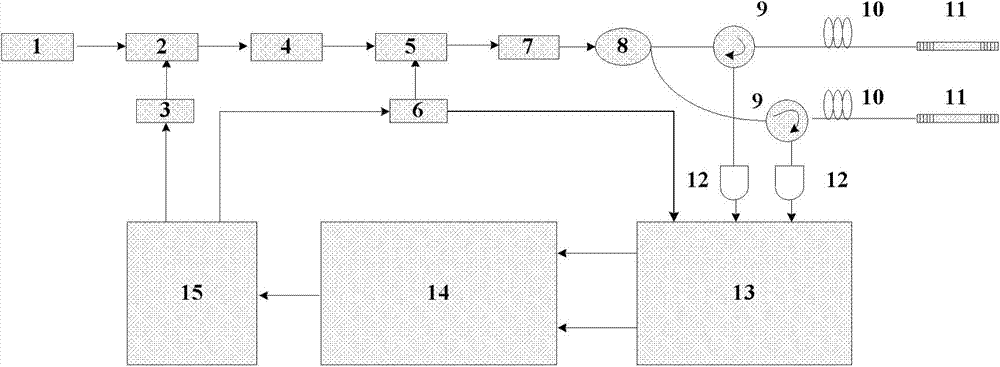
[0028] Please refer to figure 1 ,in figure 1 A structural schematic diagram of a high-precision fiber grating low-frequency strain sensing demodulation system based on laser linear sweep modulation technology and PDH frequency-locked sensing technology provided by the present invention.

[0029] Such as figure 1 As shown, the high-precision fiber grating low-frequency strain sensing demodulation system includes:

[0030] A narrow linewidth laser 1 is used to provide a narrow linewidth laser light source for the entire demodulation system;

[0031] The electro-optic / acousto-optic modulator 2 is used to modulate the laser output from the narrow-linewidth laser 1 according to the linear frequency modulation signal generat...


PUM


Abstract

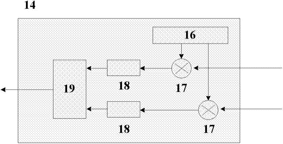
The invention discloses a fiber bragg grating low-frequency strain sensing demodulation system which comprises a narrow linewidth laser, an electro-optic / acoustic optical modulator, a radio-frequency signal generator, an electro-optic phase modulator, a phase modulation signal generator, a coupler, a first fiber bragg grating sensor, a second fiber bragg grating sensor, a photoelectric detector, a data acquisition card and a strain demodulation module. The narrow linewidth laser provides a narrow linewidth laser source for the whole demodulation system, the electro-optic / acoustic optical modulator modulates the laser source according to a chirp signal generated by the radio-frequency signal generator generating the chirp signal, and the electro-optic phase modulator performs phase modulation on the modulated laser source according to a sinusoidal modulation signal generated by the phase modulation signal generator generating the sinusoidal modulation signal. The coupler divides the laser source subjected to the phase modulation into two paths, the first fiber bragg grating sensor and the second fiber bragg grating sensor generate two paths of fiber bragg grating reflectance spectra under scanning of the two paths of the laser sources, the photoelectric detector performs photovoltaic conversion on the two paths of the fiber bragg grating reflectance spectra, the data acquisition card outputs two paths of optical fiber sensing digital signals, and the strain demodulation module is used for demodulating the two paths of the optical fiber sensing digital signals.

Description

technical field [0001] The invention relates to the field of optical fiber technology, in particular to a high-precision optical fiber grating low-frequency strain sensing demodulation system based on laser linear sweep modulation technology and PDH frequency-locked sensing technology. Background technique [0002] Fiber Bragg Grating (FBG) sensor has been a research hotspot in the field of fiber optic sensing for more than two decades, and has been widely used in strain measurement of smart materials and structures. Fiber Bragg grating sensors have many advantages such as small size, fast response speed, wide range of linear response, and easy reuse. The strain measurement accuracy of FBG strain interrogators widely used in the market is generally 1με, which can meet general application requirements. However, if FBG is to be applied to the observation of terrain deformation, the accuracy of strain observation must be above 10nε, and the system needs to meet the requirements...

Claims


Application Information

Patent Timeline
IPC IPC(8): G01B11/16
Inventor 黄稳柱张文涛李芳
Owner INST OF SEMICONDUCTORS - CHINESE ACAD OF SCI
Learn More