Underflow energy dissipater with pressurized pipeline used for outflow
A technology of pressurized pipelines and energy dissipators, which is applied in water conservancy projects, marine engineering, coastline protection, etc. problems, to achieve good energy dissipation effect, improve energy dissipation effect, and reduce the effect of building scale
- Summary
- Abstract
- Description
- Claims
- Application Information
AI Technical Summary
Problems solved by technology
Method used
Image
Examples
Embodiment 1
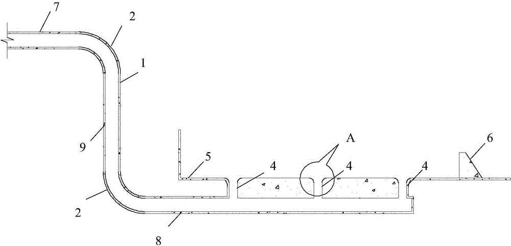
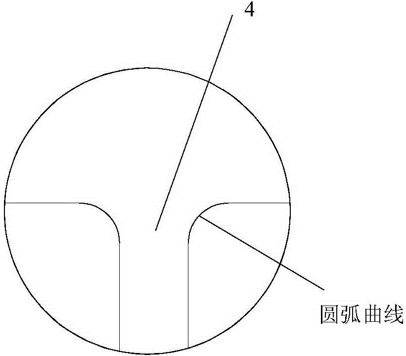
[0026] The shape, structure and connection relationship of the underflow energy dissipator provided in this embodiment are as follows: figure 1 , 3 and 4. The undercurrent energy dissipator is composed of a pressurized pipeline 1 and a stilling pool 5 . Among them, the pressurized pipeline 1 adopts a single-section elbow type pressurized pipeline suitable for low water head, specifically a circular pipe with a diameter of D=10m. The arc-shaped pressurized turning section 2 is the upper flat section 7 before the first pressurized turning section 2, and the inlet of the upper flat section 7 is connected with the outlet of the dam body overflow hole or the flood discharge tunnel. Between the sections 2 is a vertical section 9, the radius of the arc-shaped pressurized turning section between the upper flat section 7 and the vertical section 9 is 15m, the height of the vertical section 9 is 50m, and a The arc-shaped pressurized turning section 2 is the second pressurized turning...
Embodiment 2
[0029] The shape, structure and connection relationship of the underflow energy dissipator provided in this embodiment are as follows: figure 2 , 3 and 4. This submerged energy dissipator is also composed of a pressurized pipeline 1 and a stilling pool 5. The difference from Embodiment 1 is that the pressurized pipeline 1 adopts a single-section folded tube type pressurized pipeline suitable for low water head, that is, in the vertical What set up behind the section 8 is a bent shape turning section 2 that is 90 °, and all the other structures and parameters are because of being identical with embodiment 1, so omit and do not describe.
[0030] When the discharge flow is 800m 3 / s, the energy dissipation head of the subsurface energy dissipator is about 17m.
Embodiment 3
[0032] The shape, structure and connection relationship of the underflow energy dissipator provided in this embodiment are as follows: Figure 5 , 6 and 8 are shown. The undercurrent energy dissipator is composed of three pressurized pipelines 1 and a stilling pool 5 . Among them, the pressurized pipeline 1 adopts a multi-segment elbow type pressurized pipeline suitable for high water head, specifically a circular pipe with a diameter of D=10m. The arc-shaped pressurized turning section 2 is an upper flat section 7 before the first pressurized turning section 2, and the inlet of the upper flat section 7 is connected with the outlet of the dam body overflow hole or the flood discharge tunnel, and the first and second two There is a vertical section 9 between the pressure turning sections 2, and the arc-shaped pressure turning section 2 radius between the upper flat section 7 and the vertical section 9 is 15m, and the height of the vertical section 9 is 50m. There are 5 arc-s...
PUM
 Abstract
Description
Claims
Application Information
 - Generate Ideas
- Intellectual Property
- Life Sciences
- Materials
- Tech Scout
- Unparalleled Data Quality
- Higher Quality Content
- 60% Fewer Hallucinations
Browse by: Latest US Patents, China's latest patents, Technical Efficacy Thesaurus, Application Domain, Technology Topic, Popular Technical Reports.
© 2025 PatSnap. All rights reserved.Legal|Privacy policy|Modern Slavery Act Transparency Statement|Sitemap|About US| Contact US: help@patsnap.com


