
Loading device for densification via chemical infiltration in steam phase in directed flow of three-dimensional porous substrates

A porous substrate and chemical vapor infiltration technology, which is applied in the field of loading equipment for densifying three-dimensional porous substrates through directional flow vapor phase chemical infiltration, can solve the problem of uniform densification of substrates that are difficult to control flow and cannot obtain complex three-dimensional shapes , lack of densification gradient and other issues, to achieve the effect of increasing quality

Active Publication Date: 2014-07-16
GERAKL
View PDF5 Cites 6 Cited by
  • Summary
  • Abstract
  • Description
  • Claims
  • Application Information

AI Technical Summary

Problems solved by technology

[0007] However, the loader tool remains limited to directional flow densification of thin and simple shaped substrates (e.g. thin rectangular plates) and cannot obtain complex three-dimensionally shaped substrates (e.g. fiber preforms for blades) uniform densification of
Air flow is more difficult to control over substrates with complex three-dimensional shapes
Lack of control over the flow of reagent gases over the set of substrates to be densified leads to the appearance of densification gradients in the substrate
However, it is the inhomogeneity in which the substrate is densified that destroys the mechanical properties of the resulting part

Method used


Image

  • Loading device for densification via chemical infiltration in steam phase in directed flow of three-dimensional porous substrates
  • Loading device for densification via chemical infiltration in steam phase in directed flow of three-dimensional porous substrates
  • Loading device for densification via chemical infiltration in steam phase in directed flow of three-dimensional porous substrates

Examples


Embodiment Construction

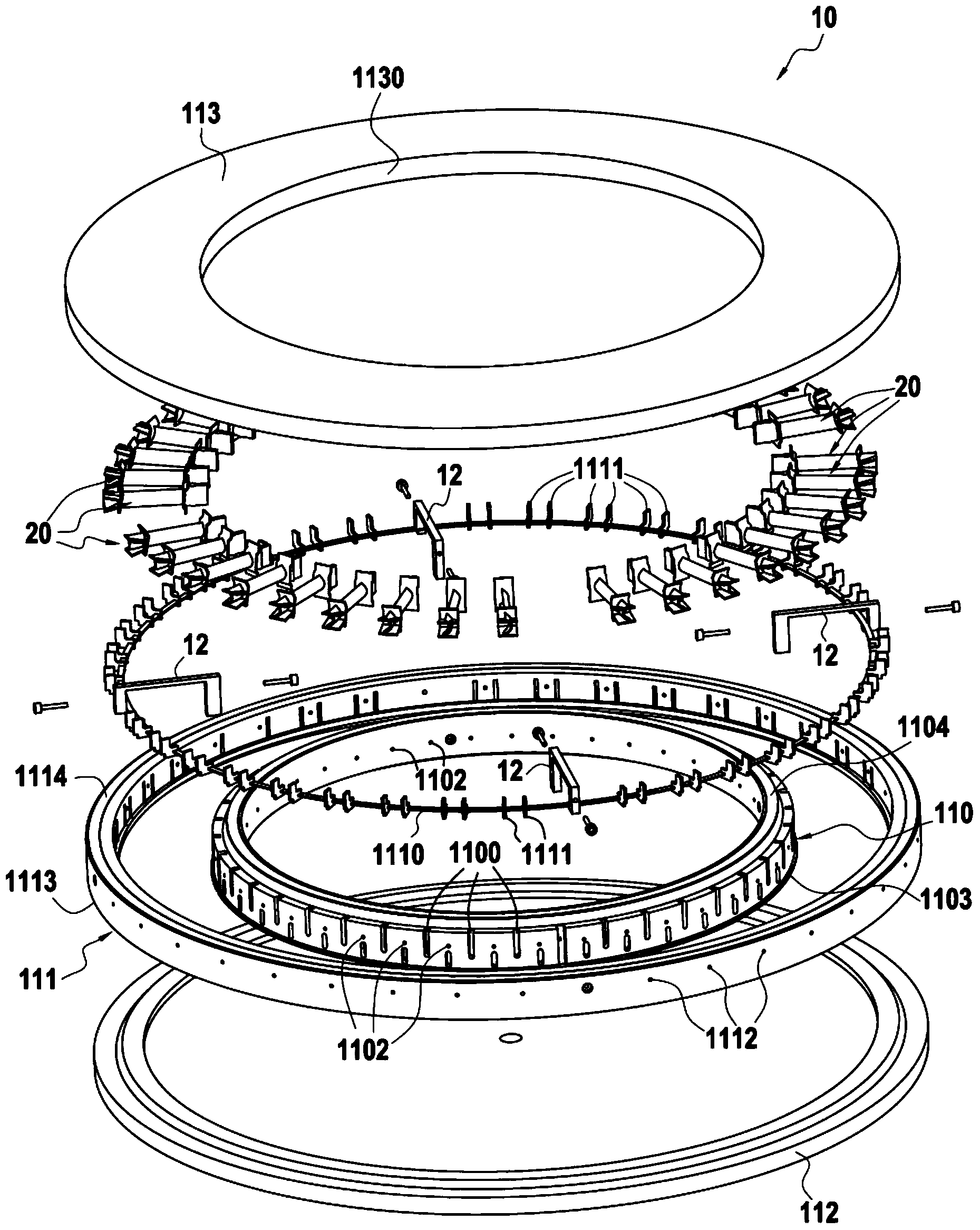
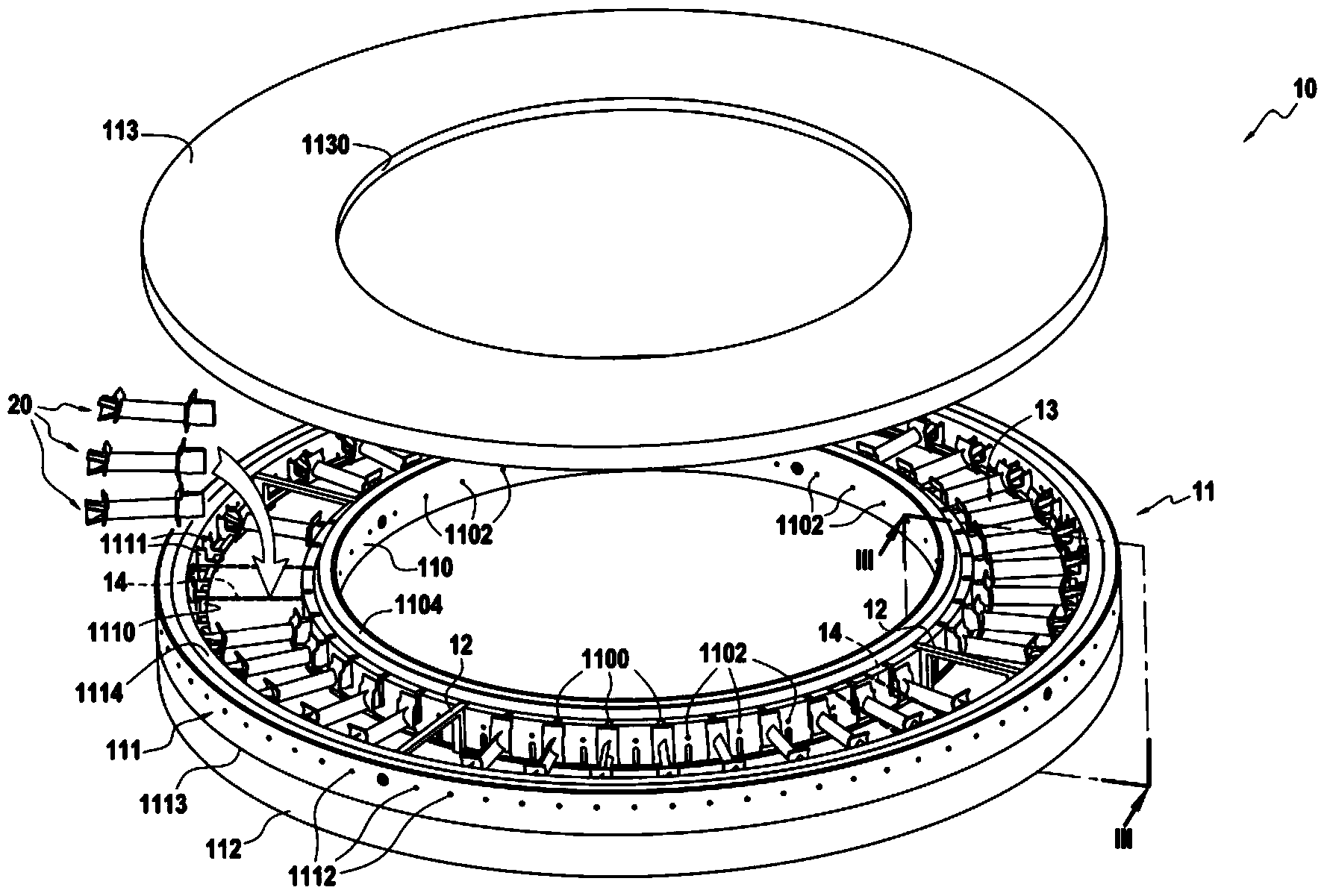
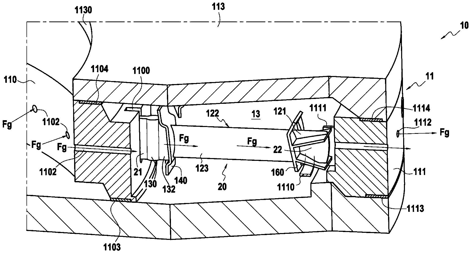
[0040] Figures 1 to 3Shown is a loader device or tool 10 which, once loaded with a substrate for densification, is inserted into a reaction chamber of an industrial plant for chemical vapor infiltration. In the presently described embodiment, the tool 10 is designed to receive a fiber preform 20 for an aeroengine blade.

[0041] Each preform 20 extends in a longitudinal direction between two ends 21 and 22 and comprises a wing 120 and a root 130 formed by a portion of greater thickness, for example with a bulb extending through a tang 132 Section of the shape ( image 3 ). The wing 120 extends in longitudinal direction between its root 130 and its tip 121 and presents in cross-section a curved profile defining a variation in thickness of two surfaces 122 and 123 corresponding respectively to the wing The suction side and the pressure side of the section 120. In the presently described embodiment, the airfoil 120 also has an inner blade platform 140 and an outer blade plat...


PUM


Abstract

Loading device (10) for densification via chemical infiltration in steam phase in directed flow, in a reaction chamber of an infiltration oven, of three-dimensional porous substrates (20) extending primarily in a longitudinal direction, said device comprising an annular loading level (11) formed by first and second annular vertical units (110, 111) distributed concentrically in relation to one another and delimiting between one another annular loading area (13) for the porous substrates to be densified. First and second plates (112, 113) respectively cover the lower element and the upper element of the annular loading area (13). The first and second annular vertical units (110, 111) each comprise supporting members (1100, 1110) distributed in the annular loading area (13) in such a manner as to define between them unit loading cells (14), each unit loading cell being intended for receiving a substrate to be densified. The device additionally comprises gas supply orifices (1102) and gas evacuation orifices (1112) in the vicinity of each unit loading cell (14).

Description

technical field [0001] The present invention relates to chemical vapor infiltration techniques used particularly when producing components from thermal structural composite materials. The invention more particularly relates to the densification of porous substrates of complex three-dimensional shape, such as fibrous preforms used in the manufacture of aeroengine blades, by depositing a matrix in said substrates to thereby densify said substrates. Background technique [0002] For the manufacture of components from composite materials, in particular from thermal structural composite materials consisting of refractory fiber preforms (e.g. Constructed using carbon fibers or ceramic fibers), common practice is to use chemical vapor infiltration methods. Examples of such components are propeller nozzles made of carbon-carbon (C-C) composites, brake discs made of C-C composites, especially for aircraft actuators, or ceramic matrix Blades made of composite material (CMC). [000...

Claims


Application Information

Patent Timeline
Patent Type & Authority Applications(China)
IPC IPC(8): C23C16/04
CPCC23C16/045C23C16/455C23C16/458
Inventor S·伯特兰F·拉穆鲁S·古雅尔
Owner GERAKL
Learn More