Introducing screw for biogas plants

A technology for conveying screws and screws, which is applied to conveyors, conveyor objects, biochemical equipment and methods, etc., can solve the problems of complex conveying screws, error-prone support and operation, etc., and achieve high-efficiency compaction and reliable conveying. Effective for compaction and reliable conveying

Active Publication Date: 2014-07-16
HUGO VOGELSANG MASCHINENBAU GMBH
View PDF9 Cites 0 Cited by
  • Summary
  • Abstract
  • Description
  • Claims
  • Application Information

AI Technical Summary

Problems solved by technology

Although the arrangement has proven to be advantageous accordingly, the conveying screw requires complex and error-prone mounting and manipulation for superposition of axial displaceability and rotation

Method used


Image

  • Introducing screw for biogas plants
  • Introducing screw for biogas plants
  • Introducing screw for biogas plants

Examples


Embodiment Construction

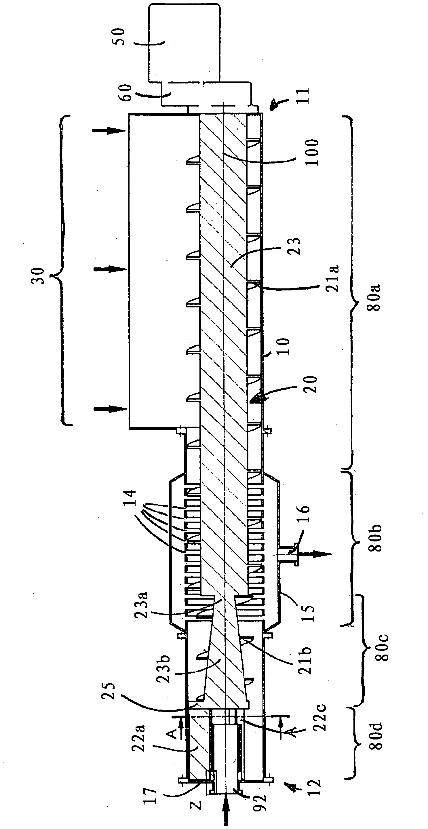
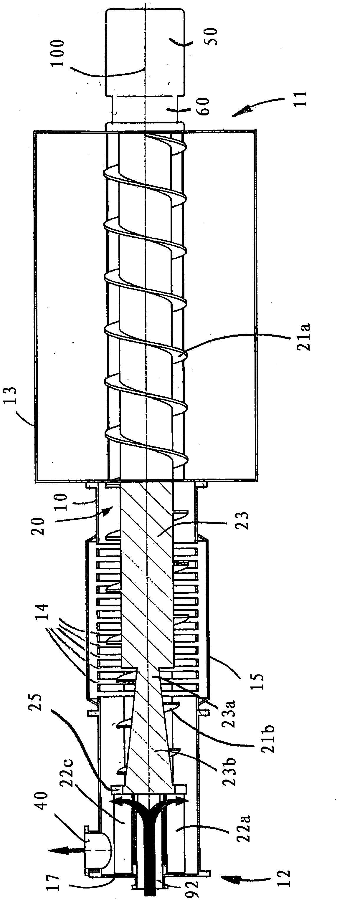
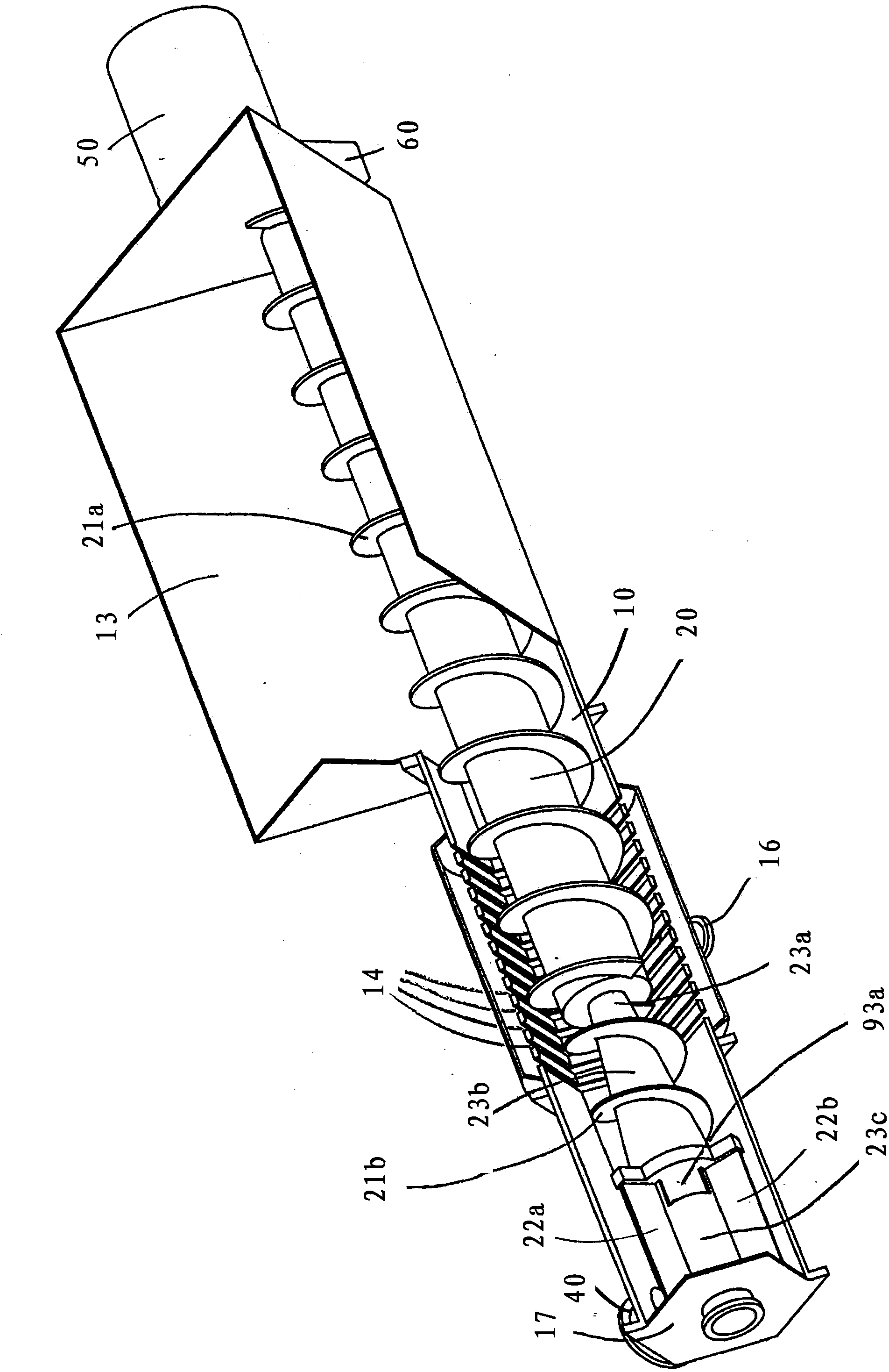
[0039] figure 1 , 2 and 3 show a screw conveyor 1 which basically comprises a screw tube 10 in which a conveyor screw 20 is mounted rotatably about a longitudinal axis 100 . The conveyor screw has a conveyor screw core 23 and screw wings 21a, 21b, 22a-c.

[0040] The inlet 30 extends from the first end 11 of the screw tube 10 over approximately half the total length of the screw tube 10 in the axial direction in the direction of the second end 12 of the screw tube 10 . The inlet 30 is designed as a screw chute 13 and enables the radial introduction of organic solids into the screw tube 10 .

[0041] In the region of the second end 12 there is an outlet 40 configured as a pipe flange, which also extends radially and whose discharge direction is rotated by 90° relative to the longitudinal axis 100 relative to the direction of entry of the organic solids into the inlet 30 .

[0042] At the first end 11 of the screw tube 10 , the electric drive motor 50 is flanged to the housin...


PUM


Abstract

The invention relates to a screw conveyor for introducing organic materials into a biogas fermenter that is under internal gas pressure. The invention further relates to a biogas plant having such a screw conveyor and to a method for feeding organic materials to such a biogas plant. According to the invention, the plug section has an expansion region, in which the passage cross-section between the conveying screw and the screw pipe is expanded in the conveying direction, and a contraction region lying after the expansion region in the conveying direction, in which contraction region the passage cross-section between the conveying screw and the screw pipe is reduced in the conveying direction.

Description

technical field [0001] The invention relates to a screw conveyor for feeding organic material into a biogas fermenter under gaseous internal pressure. Another aspect of the invention relates to a biogas plant with such a screw conveyor and a method for loading such a biogas plant with organic solids. Background technique [0002] In fermentation plants, combustible gases are produced by the fermentation of organic material in fermenters, usually by the generation of methane. The fermenter is generally operated here with a gaseous internal pressure which is created by hermetically sealing the fermenter and controlled discharge of the biogas produced therein. The fermenter can be loaded with organic solids continuously or quasi-continuously (batch) in order to maintain the fermentation process. The internal pressure in the fermenter must be overcome or maintained and undesired escape of material from the fermenter must be prevented not only during loading but also after load...

Claims


Application Information

Patent Timeline
Patent Type & Authority Applications(China)
IPC IPC(8): C12M1/107
CPCC12M21/04C12M33/16B65G33/14Y02E50/30B65G33/22B65G45/22B65G2812/0538
Inventor H·福格申
Owner HUGO VOGELSANG MASCHINENBAU GMBH
Why Eureka
Try Eureka