Damping coupler

A coupling and damping technology, which is applied in the direction of couplings, elastic couplings, mechanical equipment, etc., can solve the problems of inconvenient installation and disassembly, poor precision, poor alternating load and impact load, etc., and achieve installation and disassembly Convenience, significant shock absorption effect, good tightening effect

Active Publication Date: 2014-07-16
天津龙创恒盛实业有限公司
View PDF9 Cites 1 Cited by
  • Summary
  • Abstract
  • Description
  • Claims
  • Application Information

AI Technical Summary

Problems solved by technology

The intermediate body of the existing shaft coupling is a plum-shaped hard material, which has poor shock absorption effect and is prone to resonance and damage to the equipment; and the clamping sleeve and the shaft are fixedly connected by a key connection, while the axial direction Connected by bolts, there are problems of poor precision, poor ability to withstand alternating loads and impact loads, easy backlash, and inconvenient installation and disassembly

Method used


Image

  • Damping coupler
  • Damping coupler
  • Damping coupler

Examples


Embodiment Construction

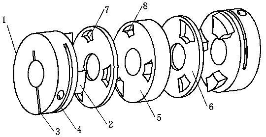
[0025] Such as Figure 1-3 As shown, the technical solution of the present invention is: a damping coupling, comprising two clamping sleeves 1 and an intermediate body, the two clamping sleeves are respectively installed on both sides of the intermediate body,

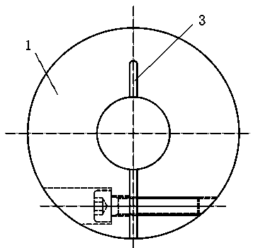
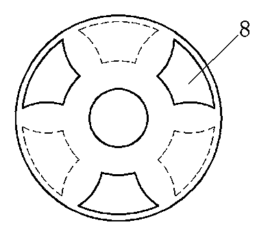
[0026] The clamping sleeve includes a circular body 1 and a plurality of metal claws 2 extending in the axial direction along the end face of the circular body 1 and arranged in an array along the circumferential position of the end face. The axial direction is formed between two adjacent metal claws 2 The circular body 1 passes through its central position and radially is provided with a gap groove 3 from the left end surface to the right end surface, the width is 2mm higher than the radius of the circular body 1, and the side surface of the circular body 1 is provided with a through The tightening bolt passing through the gap groove 3 is provided with a radial slot 4 with a width of 2 mm higher than the radius of the ro...


PUM


Abstract

The invention provides a damping coupler. Two clamping sleeves are installed on the two sides of a middle body respectively. Each clamping sleeve comprises a circular body and a plurality of metal claws stretching out in the axial direction of the end face of the circular body and distributed at the positions in the circumferential direction of the end face in an array mode, an axial gap is formed between every two adjacent metal claws, the circular bodies are provided with gap slots penetrating the centers of the circular bodies and formed in the radial direction, the side surfaces of the circular bodies are provided with fastening bolts penetrating through the gap slots, and the side surfaces of the circular bodies and the right sides of the fastening bolts are respectively provided with a radial cut groove. Flexible middle body pieces of the middle body are installed on the two sides of a hard middle body piece respectively, and the flexible middle body pieces are provided with through holes with the same shape as the metal claws. The hard middle body piece is evenly divided into a left part and a right part in the radial direction, the left part and the right part are connected into a whole, the two sides of the hard middle body are both provided with grooves with the same shape as the metal claws, and a groove is formed in the right side of the axial direction between every two adjacent grooves in the left side. The damping coupler has the advantages of being high in torsional rigidity, high in response, simple in structure, capable of effectively reducing vibration and suppressing resonance and convenient to install and disassemble.

Description

[0001] Technical field [0002] The invention belongs to the field of couplings, and in particular relates to a damping coupling. Background technique [0003] Couplings are mainly used for connection in mechanical transmission and are the main parts in mechanical transmission. It is mainly used to connect the driving shaft and the driven shaft to transmit motion and torque. It can compensate for eccentricity, deflection angle, and axial displacement caused by manufacturing errors, installation errors, post-load deformation and temperature changes. The intermediate body of the existing coupling is a plum-shaped hard material, which has poor damping effect and is likely to cause resonance and damage the equipment; and the clamping sleeve and the shaft are fixedly connected by a key connection, and the axial direction The upper is connected by bolts, which has the problems of poor accuracy, inability to withstand alternating loads and poor impact loads, easy backlash, and inco...

Claims


Application Information

Patent Timeline
Patent Type & Authority Applications(China)
IPC IPC(8): F16D3/56
Inventor 杨松楷
Owner 天津龙创恒盛实业有限公司
Why Eureka
Try Eureka