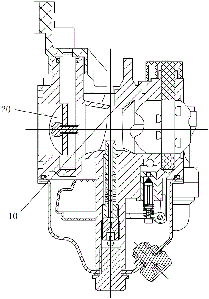
A main oil system structure and a carburetor with the structure
A carburetor and oil system technology, applied in the direction of machines/engines, etc., can solve the problems of rising and falling emission values, failure to meet environmental protection, etc., and achieve the effects of promoting rarefied combustion, improving atomization performance, and reducing emissions
- Summary
- Abstract
- Description
- Claims
- Application Information
AI Technical Summary
Problems solved by technology
Method used
Image
Examples
Embodiment Construction
[0070] Below in conjunction with accompanying drawing, structural principle and working principle of the present invention are specifically described:
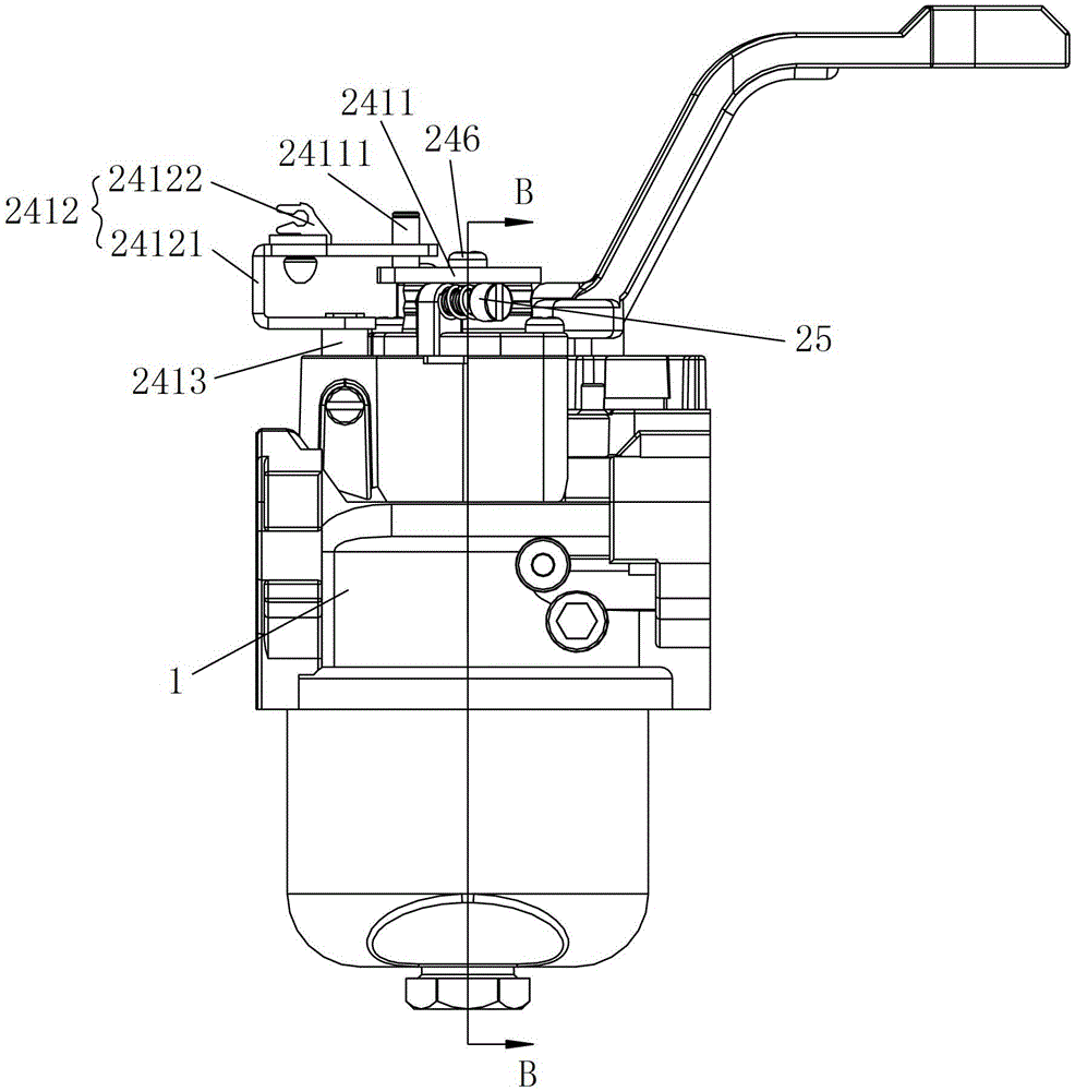
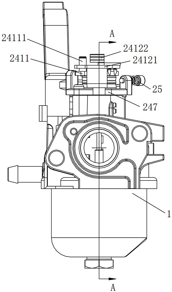
[0071] see figure 2 - Figure 4 , figure 2 It is a structural schematic diagram of a carburetor according to an embodiment of the present invention, image 3 for figure 2 left view of Figure 4 for figure 2 top view. The carburetor of the present invention comprises a carburetor body 1 and a main oil system structure 2, wherein, the structure of the carburetor body 1 and the structures, functions, connection relations and details of other parts such as air holes 13, float chambers 14, etc. Mutual positional relationship etc. are relatively mature prior art, and will not be repeated here, and only the main oil system mechanism 2 of the present invention will be described in detail below.
[0072] see Figure 5A - Figure 6 , Figure 5A for image 3 A-A sectional view of (Venturi open position), Figure 5B for ...
PUM
 Abstract
Description
Claims
Application Information
 - R&D Engineer
- R&D Manager
- IP Professional
- Industry Leading Data Capabilities
- Powerful AI technology
- Patent DNA Extraction
Browse by: Latest US Patents, China's latest patents, Technical Efficacy Thesaurus, Application Domain, Technology Topic, Popular Technical Reports.
© 2024 PatSnap. All rights reserved.Legal|Privacy policy|Modern Slavery Act Transparency Statement|Sitemap|About US| Contact US: help@patsnap.com


