
escape pod thruster

A technology of pushing devices and escape cabins, which is applied in transportation and packaging, special-purpose vessels, underwater operation equipment, etc. It can solve the problems of inaccessibility of seawater, great safety hazards, and inability to float, etc., and achieves compact structure and high thrust load Large, safe and reliable working process

Active Publication Date: 2016-04-13
中国船舶重工集团公司第七〇二研究所
View PDF6 Cites 0 Cited by
  • Summary
  • Abstract
  • Description
  • Claims
  • Application Information

AI Technical Summary

Problems solved by technology

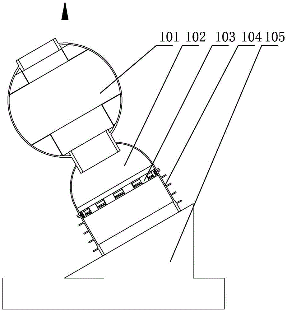
In actual use, after the pressure is equalized underwater and the locking ring 103 and the flange are released in an emergency, the escape cabin 101 can generally float up by relying on its own buoyancy; but there may also be a phenomenon that it cannot float up
The reasons are: first, under the hydrostatic pressure, the sealing ring and the sealing groove of the flange are closely attached for a long time, and the seawater cannot flow into their joint surfaces, so that there is still a large gap between the upper and lower butt joint flanges of the escape cabin. Pressure (indicated by symbol F)
Second, if an underwater accident occurs, the deep-sea workstation 105 is in a tilted state, and after the escape cabin 101 is released in an emergency, it will float vertically by buoyancy, and there will be a phenomenon of "stuck" between the locking ring 103 and the docking flange
There is a big security risk

Method used


Image

  • escape pod thruster
  • escape pod thruster
  • escape pod thruster

Examples


Embodiment Construction

[0026] The specific implementation manner of the present invention will be described below in conjunction with the accompanying drawings.

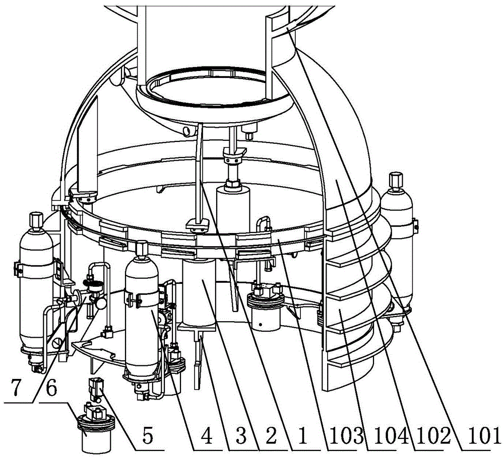
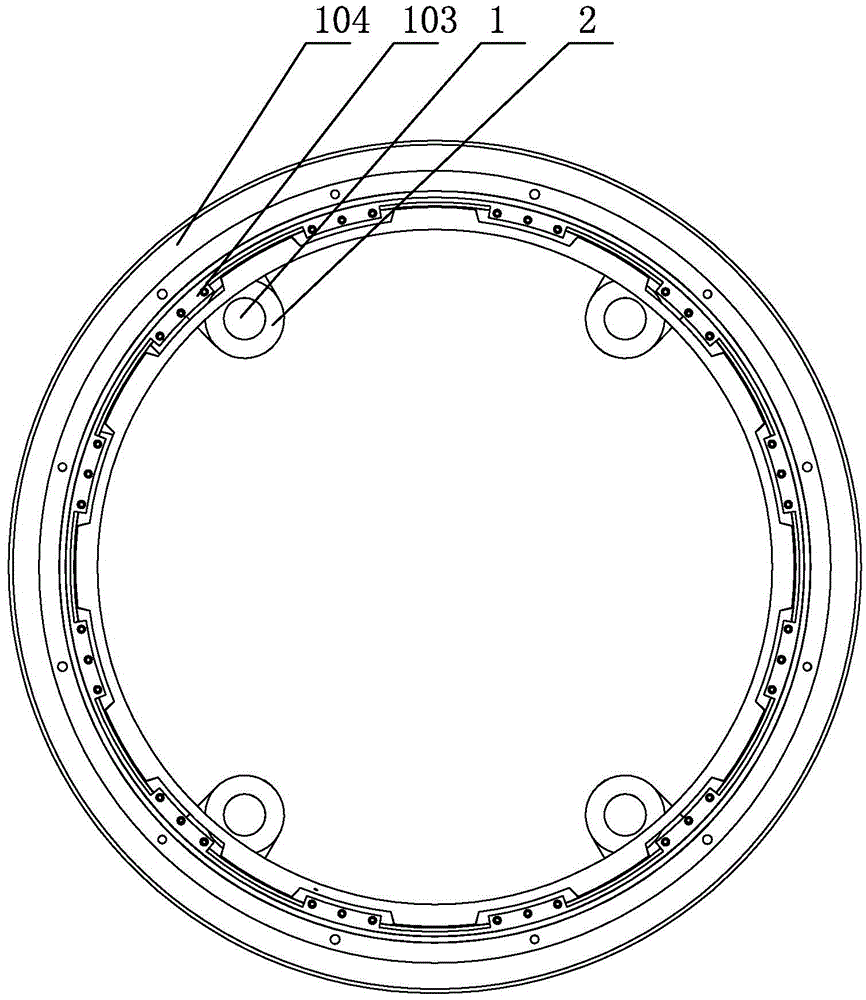
[0027] Such as figure 1 , figure 2 and image 3 As shown, the escape cabin jacking device of this embodiment includes a workstation docking fence 104 connected to a deep-sea workstation 105, an escape cabin docking fence 102 is installed on the top of the workstation docking fence 104 through a locking ring 103, and an escape cabin docking fence 102 is installed on the top of the escape cabin docking fence 102. The cabin 101 is located in the inner ring surface of the docking fence 104 of the workstation, and multiple groups of pushing devices are evenly installed. The structure of the pushing device is: including the mounting seat 3, the oil cylinder 2 is fixed on the mounting seat 3, and the piston rod head of the oil cylinder 2 A counter force support 1 is installed through the connector, and the top of the counter force support 1 ab...


PUM


Abstract

The invention relates to an escape cabin ejecting and pushing device. The escape cabin ejecting and pushing device comprises a work station butt joint fence connected with a deep sea work station, wherein an escape cabin butt joint fence is arranged on the top of the work station butt joint fence through a locking ring, an escape cabin is arranged on the top of the escape bin butt joint fence, and multiple ejecting and pushing device bodies are evenly arranged in the inner annular face of the work station butt joint fence. Each ejecting and pushing device body structurally comprises an installation base, wherein an oil cylinder is fixed to the installation base, the head of a piston rod of the oil cylinder is provided with a reaction force support through a connecting piece, and the top portion of the reaction force support is connected with an ejecting and pushing point on the circumference of the bottom of the escape cabin butt joint fence in a butt joint mode. Each ejecting and pushing device body further comprises a power source of the corresponding oil cylinder, wherein a plurality of energy accumulators are arranged on the outer circumferential face of the work station butt joint fence at intervals and connected with an electromagnetic ball valve through hydraulic pipelines, and the electromagnetic ball valve is arranged in a pressure-resistant shell. Each ejecting and pushing device body further comprises a control cable used for controlling opening and closing of the corresponding electromagnetic ball valve. The working process is safe and reliable, and free floating of the escape cabin deep sea work station can be ensured.

Description

technical field [0001] The invention relates to the technical field of deep-sea escape equipment, in particular to an escape cabin jacking device, which is used on a deep-sea workstation to provide extra jacking force for the escape cabin and assist it to escape from the station and float freely. Background technique [0002] The deep-sea workstation has its own escape cabin. When an emergency occurs, all personnel enter the escape cabin, connect the release device to work, rotate the locking ring at a certain angle, and release the fixed connection between the escape cabin and the deep-sea workstation. The escape cabin relies on itself Buoyancy rises to the surface for assistance. [0003] Such as figure 1 As shown, the workstation docking fence 104 is installed on the inclined surface of the deep sea workstation 105, and the escape cabin docking fence 102 is installed on the top of the workstation docking fence 104 through the locking ring 103, and the escape cabin 101 is...

Claims


Application Information

Patent Timeline
Patent Type & Authority Patents(China)
IPC IPC(8): B63G8/41B63C11/52
Inventor 吴世海王永军张震余俊
Owner 中国船舶重工集团公司第七〇二研究所
Learn More