
Turning method and turning positioning device for UF outer spider short-shanked precision forgings

A positioning device, the technology of the outer planetary wheel, applied in the field of high-speed transmission, can solve the problems of scrap parts, out of tolerance on the outer circle of the head, and inability to mill the fairway and spherical surface.

Active Publication Date: 2014-07-16
SHANGHAI GKN DRIVE SYST
View PDF5 Cites 1 Cited by
  • Summary
  • Abstract
  • Description
  • Claims
  • Application Information

AI Technical Summary

Problems solved by technology

[0006] However, the above-mentioned finishing process has the following defects: the centerline of the shank of the short shank blank of the UF outer star wheel is associated with the centerline of the die, so the center hole on the end face of the handle is also associated with the centerline of the die; The centerline of the inner cavity of the head of the short handle blank is related to the centerline of the punch, so the center of the three-jaw short arc positioning device is also related to the centerline of the punch
Since the centerline of the die and the centerline of the punch do not coincide, the centerline formed by the center hole of the shank and the center of the three-jaw short arc positioning device is used as the positioning reference. After turning the outer circle of the shank and the outer circle of the head, The whole part will be crooked, which cannot eliminate the deviation between the centerline of the head cavity and the centerline of the shank during the rough machining stage, resulting in the centerline of the part being non-parallel to the centerline of the six fairways, at the center of the top shank When the outer circle runout of the head is measured by the spherical surface of the inner cavity of the hole and the head, the outer circle runout of the head often occurs out of tolerance, which leads to the fact that the ball track and the spherical surface are often not milled, and parts are scrapped.

Method used


Image

  • Turning method and turning positioning device for UF outer spider short-shanked precision forgings
  • Turning method and turning positioning device for UF outer spider short-shanked precision forgings
  • Turning method and turning positioning device for UF outer spider short-shanked precision forgings

Examples


Embodiment Construction

[0066] The implementation of the present invention will be illustrated by specific specific examples below, and those skilled in the art can easily understand other advantages and effects of the present invention from the contents disclosed in this specification.

[0067] It should be noted that the structures, proportions, sizes, etc. shown in the drawings attached to this specification are only used to match the content disclosed in the specification, for those who are familiar with this technology to understand and read, and are not used to limit the implementation of the present invention. Limiting conditions, so there is no technical substantive meaning, any modification of structure, change of proportional relationship or adjustment of size, without affecting the effect and purpose of the present invention, should still fall within the scope of the present invention. The disclosed technical content must be within the scope covered. At the same time, terms such as "upper"...


PUM


Abstract

The invention provides a turning method for UF outer spider short-shanked precision forgings. The method includes the sequential steps of sleeving a turning positioning device, which comprises a fixed base and a connecting part, with a UF outer spider short-shanked precision forging, providing the outside of the connecting part with a plurality of lanes which radially protrude, which face first lanes and which have center lines parallel to the center axis of the turning positioning device; by using the center axis of the turning positioning device as a positioning reference, turning the end face of a shank of a UF outer spider short-shanked blank, drilling a center hole in the end face of the shank, and turning the outside of the shank and the outside of a head of the UF outer spider short-shanked blank. The turning method has the advantages that the center axis of the turning positioning device is used as the positioning reference constantly during turning the UF outer spider short-shanked blank, jitter of the outside of the head of a turned UF outer spider is never out of tolerance, and subsequent smooth milling of all first lanes of the UF outer spider is facilitated.

Description

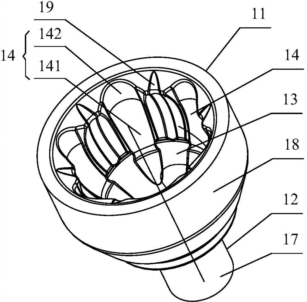
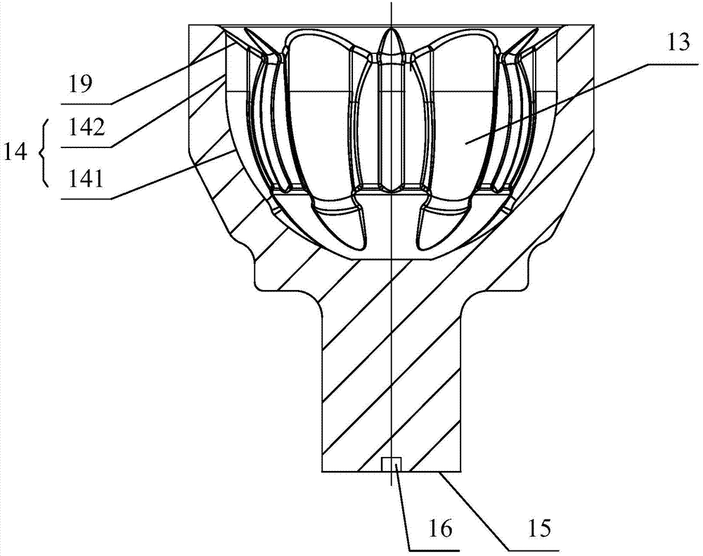
technical field [0001] The invention relates to the field of constant velocity transmission of automobiles, in particular to a turning method and a turning positioning device for a short-shank precision forging of a UF outer star wheel. Background technique [0002] In the constant velocity transmission system of automobiles, constant velocity universal joints are usually used to connect two shafts whose axes do not coincide, and make the two shafts transmit motion at the same angular velocity. The constant velocity universal joint generally includes parts such as outer star wheel, inner star wheel, steel ball and steel ball cage. According to the different models of the constant velocity universal joint, the specific structure of each part will be different. figure 1 and figure 2 It is a schematic diagram of the structure of the short-shank precision forging of the UF outer planetary wheel. It can be seen from the figure that the short-shank precision forging of the UF al...

Claims


Application Information

Patent Timeline
IPC IPC(8): B23P13/02B23Q3/00
CPCB23B1/00B23Q3/00
Inventor 王德林陆有根
Owner SHANGHAI GKN DRIVE SYST
Learn More