
Topogram From A Spiral Reconstruction

A positioning piece and spiral technology, applied in the field of computer program products, can solve problems such as distortion cannot be compensated

Active Publication Date: 2014-07-16
SIEMENS HEALTHCARE GMBH
View PDF5 Cites 7 Cited by
  • Summary
  • Abstract
  • Description
  • Claims
  • Application Information

AI Technical Summary

Problems solved by technology

The distortions that occur in the central projection cannot thus be compensated, so that the positioning plates produced by known methods also have distortions

Method used


Image

  • Topogram From A Spiral Reconstruction
  • Topogram From A Spiral Reconstruction

Examples


Embodiment Construction

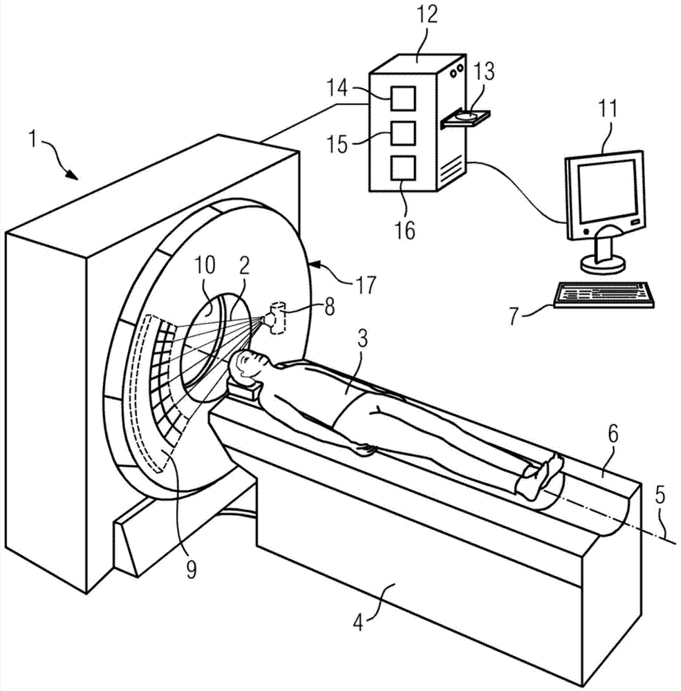
[0035] figure 1 A computed tomography system according to the invention is shown. The computed tomography system shown here has an imaging unit 17 which includes an x-ray source 8 and an x-ray detector 9 . The imaging unit 17 is rotated about the longitudinal axis 5 during the helical imaging for determining the scout according to the invention, and the x-ray source 8 emits the x-ray fan beam 2 during the helical imaging. The x-ray source 8 is an x-ray tube in the example shown here. In the example shown here, the x-ray detector 9 is a row detector with several rows.

[0036] During the acquisition of images by means of the computer tomography apparatus according to the invention, in particular during the acquisition of radiographs or diagnostic images, the patient 3 lies on a patient couch 6 . The patient couch 6 is connected to the couch base 4 in such a way that it supports the patient couch 6 with the patient 3 . The patient couch 6 is designed to move the patient 3 th...


PUM


Abstract

The invention relates to a method for determining a topogram, a computed tomography system and a computer program product. An embodiment uses such a spiral acquisition to reconstruct a spatial three-dimensional image of the examination region. The method also includes establishing a topogram of the examination region by parallel projection of the image along a projection direction. An embodiment of the invention allows distortion-free acquisition of a topogram, as a reconstructed spatial three-dimensional image can simply be projected in a parallel manner along a projection direction. An embodiment also allows multiple topograms to be established easily with just one acquisition, in that the reconstructed image of the examination region is projected in a parallel manner along different directions. An embodiment of the invention also allows particularly fast acquisition of a topogram, in particular in the clinical environment, as the rotating part of the gantry does not have to be stopped for the spiral acquisition.

Description

technical field [0001] The invention relates to a method and a computed tomography apparatus for determining a scoliosis slice as well as a computer program product. Background technique [0002] Computed tomography is an imaging method that is primarily used in medical diagnosis. If a spatial three-dimensional image, 3D image for short, of the examination region is to be recorded by means of computed tomography, the recording unit of the computed tomography device rotates around the examination region. The imaging unit includes an X-ray source and an X-ray detector. A projection is recorded in each case at different positions of the recording unit on its circular path. The different projections are recorded here at different projection angles. In the following, the projection angle refers to the radial angle of the recording unit in its plane of rotation; that is to say the angle enclosed, for example, by the x-ray source-x-ray detector connection axis and a fixed axis p...

Claims


Application Information

Patent Timeline
IPC IPC(8): A61B19/00A61B6/03
CPCA61B6/027A61B6/032A61B6/4014A61B6/542G06T11/005G06T11/006G06T11/003
Inventor B.施米特M.赛德尔梅尔
Owner SIEMENS HEALTHCARE GMBH
Learn More