Sheet metal stamping device

A technology of stamping device and sheet metal parts, applied in the field of sheet metal parts stamping device, can solve the problems such as the inability of the buffer structure to achieve the buffer effect, increase the consumption of raw materials of the sheet metal material plate, and the stamping process cannot be carried out normally, so as to shorten the abnormal processing. The effect of reducing time, reducing losses and reducing production costs

Active Publication Date: 2016-01-13
江门市广润轨道交通实业有限公司
View PDF7 Cites 0 Cited by
  • Summary
  • Abstract
  • Description
  • Claims
  • Application Information

AI Technical Summary

Problems solved by technology

[0003] In the stamping process of sheet metal parts, when the stamping head punches the sheet metal material plate, the blanked sheet metal part will be removed, and obvious curling or protrusions will appear on the edge of the remaining material plate, making the material plate The quality of the sheet metal part will decrease during the next punching, and it will increase the raw material consumption of the sheet metal material plate and increase the production cost; however, when the punching head is in contact with the sheet metal material plate, the buffer structure usually installed on the lower die base It will be deformed and interfere with the inner wall of the lower mold base. When the amount of grinding of the upper and lower mold bases is small, (the amount of grinding is the amount of the convex and concave molds reserved during the manufacturing process. The amount of wear means that the cutting edge of the punch and die will wear out during the use of the mold. The punch and die that do not have a grinding amount will be scrapped directly, and if there is any, it can be repaired. smaller), the cushioning structure cannot achieve the predetermined cushioning effect, and eventually the stamping process cannot be carried out normally

Method used


Image

  • Sheet metal stamping device
  • Sheet metal stamping device
  • Sheet metal stamping device

Examples


Embodiment 1

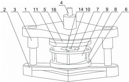
[0022] like Figure 1 to Figure 3As shown, the stamping device for sheet metal parts of the present invention includes an upper mold base 1 and a lower mold base 2, the upper mold base 1 and the lower mold base 2 are connected by a support rod 3, and the lower mold base 2 is installed on the working platform of the stamping machine. Punch head 4 is installed in described upper mold base 1, upper mold fixed plate 5 is installed on described upper mold base 1, lower mold fixed plate 6 is installed on described lower mold base 2, upper mold fixed plate 5 There is a through hole on the top, and an annular plate 7 is arranged on the lower mold fixing plate 6, and the annular plate 7 is connected with the lower mold fixing plate 6 through a plurality of screw rods 8; it also includes a rubber block 9, and the rubber block 9 It is arranged between the annular plate 7 and the lower mold fixing plate 6, and is located inside the annular ring formed by a plurality of screw rods 8. The r...

Embodiment 2

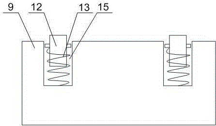
[0024] Such as figure 2 As shown, in this embodiment, on the basis of Embodiment 1, an ejector mechanism is also installed on the rubber block 9, and the ejector mechanism includes a push rod 12, a blind hole is provided on the rubber block 9, and the push rod 12 is connected to the bottom of the blind hole by a spring 13, and the diameter of the push rod 12 decreases gradually along the direction of the lower mold base 2. After the stamping head 4 punches, the rubber block 9 is compressed and deformed, the ejector rod 12 moves down, and the spring 13 is also compressed at the same time. Under the action, the formed sheet metal parts located in the middle gap of the annular plate 7 are ejected, so as to facilitate the next blanking quickly.

Embodiment 3

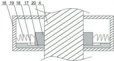
[0026] Such as figure 1 As shown, on the basis of Embodiment 1, this embodiment further includes a leveling plate 11 , the leveling plate 11 is slidably arranged on the outer wall of the stamping head 4 , and the leveling plate 11 is an annular member. When the sheet metal material plate is punched by the stamping head 4, curling or protrusions will appear on the edge of the remaining part of the material plate, and the flattening plate 11 will move downward together with the stamping head 4. When shifting, the remaining part of the material plate will not produce any curling or protrusion under the clamping action of the flat plate 11 and the annular plate 7. After the first punching is completed, adjust the material plate to continue the second punching. Cutting, thereby reducing the loss of material plates to the greatest extent, and reducing the production cost of sheet metal parts.


PUM


Abstract

The invention discloses a sheet metal part stamping device which comprises an upper die base and a lower die base. The upper die base is connected with the lower die base through a supporting rod, the lower die base is arranged on a working table of a stamping machine, a stamping head is arranged in the upper die base, a rubber block is arranged between an annular plate and a lower die fixing plate, and is arranged inside an annular ring formed by a plurality of screw rods, a sunken portion is formed in the middle of the rubber block, and is concentric with an inner hole of the annular plate, an upper surface of a stress plate and the upper surface of the annular plate are arranged on the same horizontal plane, an adjusting cylinder penetrates through the upper die base and is arranged in the through hole, the stamping head is arranged in the adjusting cylinder in a sliding mode, a fixing ring is arranged on the inner wall of the adjusting cylinder, a plurality of trapezoid-shaped grooves are formed in the fixing ring, the trapezoid-shaped grooves are radiated in the radial direction of the fixing ring, a baffle block is arranged on the trapezoid-shaped grooves, protrusions are connected with the lower portion of the baffle block, the protrusions are arranged in the trapezoid-shaped grooves in a sliding mode, the baffle block is connected with the wall of the adjusting cylinder through a torsion spring, and in the working process, the torsion spring is in the compression state.

Description

technical field [0001] The invention relates to the field of stamping headgear, in particular to a sheet metal stamping device. Background technique [0002] Sheet metal parts have the characteristics of light weight, high strength, electrical conductivity (can be used for electromagnetic shielding), low cost, and good performance in mass production. At present, they are widely used in the fields of electronic appliances, communications, automobile industry, medical equipment, etc. For example, in computer cases, mobile phones, and MP3 players, sheet metal is an essential component. The design of sheet metal parts has become a very important part of the product development process. There are many sheet metal materials suitable for stamping processing. Sheet metal materials widely used in the electronic and electrical industries include: ordinary cold-rolled plates, SPCC refers to steel ingots After being continuously rolled by a cold rolling mill into steel coils or sheets ...

Claims


Application Information

Patent Timeline
Patent Type & Authority Patents(China)
IPC IPC(8): B21D28/02B21D28/14B21D43/00B21D45/00
Inventor 陈志强
Owner 江门市广润轨道交通实业有限公司
Why Eureka
Try Eureka