
Connecting mechanism and electronic device having the same

A connection mechanism and technology for electronic devices, applied in connection, structural components of portable computers, electrical equipment casings/cabinets/drawers, etc., can solve problems such as inability to stop more stably, looseness, etc.

Active Publication Date: 2014-07-02
苏州医疗器械产业发展集团有限公司
View PDF4 Cites 8 Cited by
  • Summary
  • Abstract
  • Description
  • Claims
  • Application Information

AI Technical Summary

Problems solved by technology

However, the tight fit between the pivot shaft and the connection between the two main bodies is likely to be loosened due to repeated rotations, resulting in the inability of the two main bodies to stop at a relatively inclined angle position more stably

Method used


Image

  • Connecting mechanism and electronic device having the same
  • Connecting mechanism and electronic device having the same
  • Connecting mechanism and electronic device having the same

Examples


Embodiment Construction

[0017] The electronic device with connection mechanism of the present invention is specifically introduced by taking an all-in-one computer with a keyboard as an example. It can be understood that the electronic device includes but is not limited to all-in-one computer, mobile phone, notebook computer, e-book, etc.

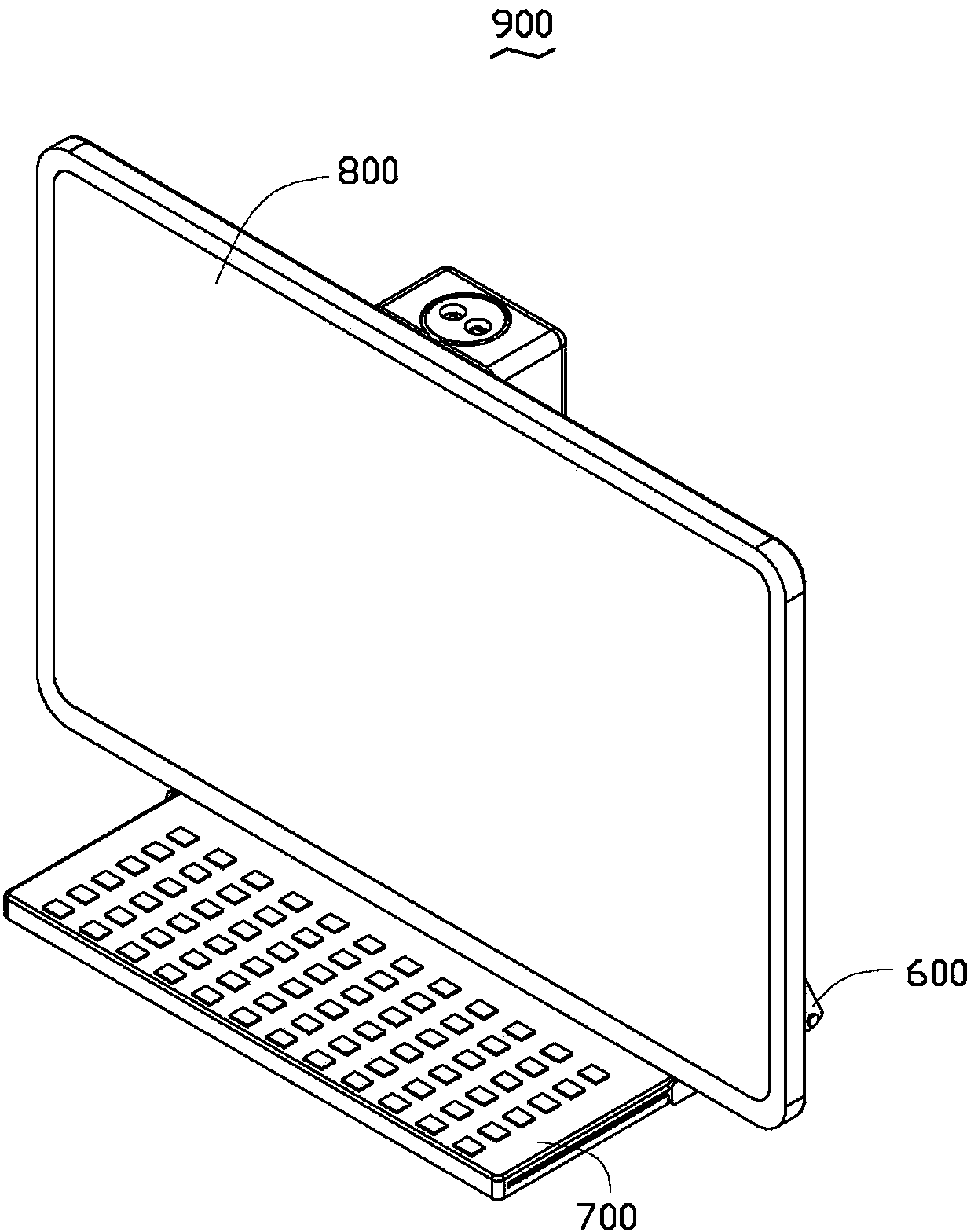
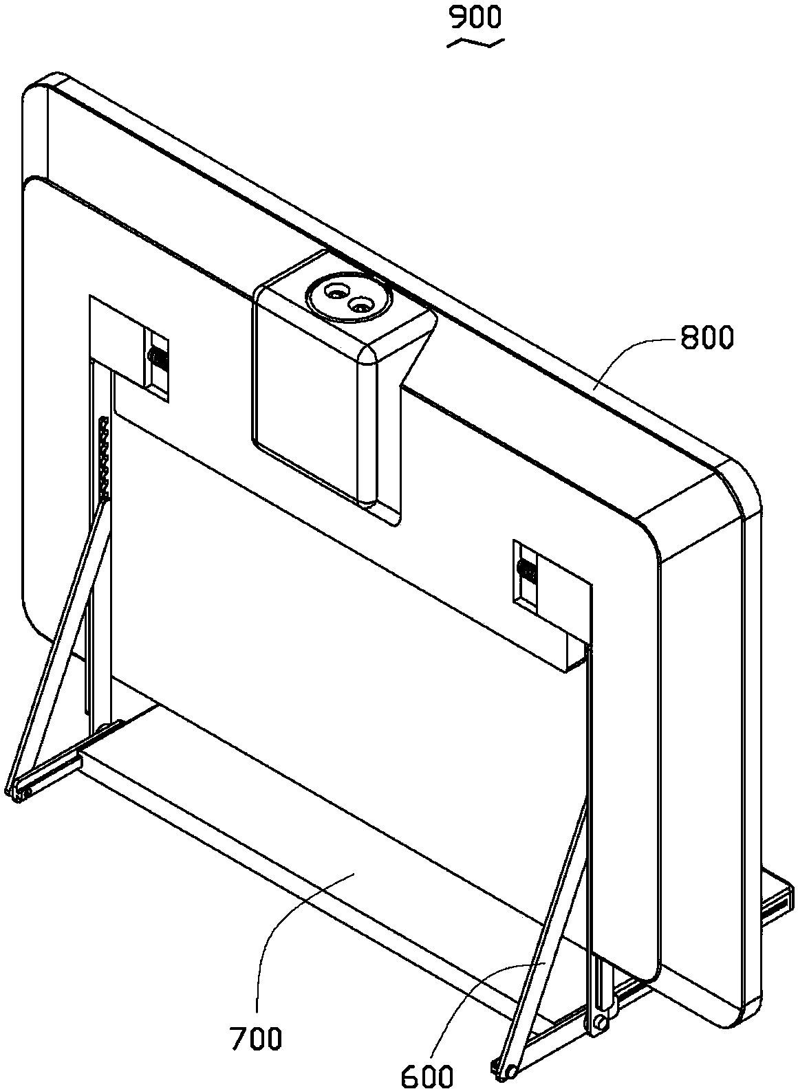
[0018] see figure 1 and figure 2 , the electronic device 900 has a first main part 800 , a second main part 700 and a connection mechanism 600 connecting the first main part 800 and the second main part 700 . The connection mechanism 600 is used for positioning the relative inclination angle between the first main part 800 and the second main part 700 , and also allows the second main part 700 to be stored on the back of the first main part 800 for easy transportation. In this embodiment, the first main part 800 is the main body of the all-in-one computer, and the second main part is the keyboard. The connection mechanism 600 connects the back of the all-in-one...


PUM


Abstract

A connecting mechanism for connecting a first unit and a second unit together is illustrated. The connecting mechanism includes a first linkage bar, a second linkage bar for being coupled to the first unit, and a third linkage bar for being slidably connected to the second unit. The first linkage bar includes a first end with a latching protrusion and an opposite second end. The second linkage bar includes a third end, an opposite fourth end, and a number of teeth. The first end is slidably connected to the second linkage bar. The latching protrusion is configured to selectively interlock with any one of the teeth of the second linkage bar. The third linkage bar includes a fifth end pivotally connected to the second end of the first linkage bar and a sixth end pivotally connected to the fourth end of the second linkage bar.

Description

technical field [0001] The invention relates to a connection mechanism and an electronic device with the connection mechanism. Background technique [0002] At present, electronic devices such as flip phones and notebook computers have two main bodies, the main body of the display screen and the main body of the keyboard, and the two main bodies are pivotally connected to the same pivot shaft to realize the connection of the two. When the electronic device is in use, the two main bodies rotate relative to the pivot shaft and stop by the frictional force tightly fitted between them, and the two main bodies are in a fixed state at an angle. When the electronic device is in a standby or shutdown state, the two main bodies rotate by means of the pivot shaft to overlap each other, so as to save volume and facilitate transportation. However, the tight fit between the pivot shaft and the connection between the two main bodies is likely to be loosened due to multiple rotations, res...

Claims


Application Information

Patent Timeline
Patent Type & Authority Applications(China)
IPC IPC(8): H05K5/02G06F1/16
CPCG06F1/1624G06F1/1616H05K5/0226G06F1/1601Y10T403/32057
Inventor 陈州
Owner 苏州医疗器械产业发展集团有限公司
Learn More