
Upper arm of robot

A robot and upper arm technology, applied in the field of robotics, can solve the problems affecting the flexibility of the robot arm, shorten the service life of the motor, and the timing belt 110 is too long, etc., and achieve the effects of adjustable gear clearance, increased selection range, and simple assembly

Active Publication Date: 2014-07-02
成都三译智能技术有限公司
View PDF5 Cites 24 Cited by
  • Summary
  • Abstract
  • Description
  • Claims
  • Application Information

AI Technical Summary

Problems solved by technology

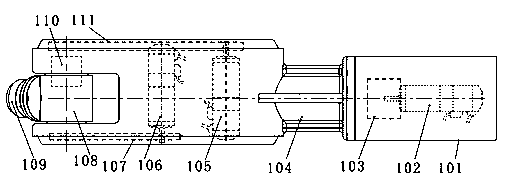
[0005] B. The control cables of the servo motor 105 of the fifth joint and the servo motor 106 of the sixth joint need to bypass the reducer 103 of the fourth joint, and at the same time, the cables need to rotate together with the rotating arm 104 of the fourth joint. On the one hand, the cables need to be bent. On the other hand to be twisted, it is easy to break and malfunction;
[0006] C. The fifth joint servo motor 105 and the sixth joint servo motor 106 are placed in the fourth joint rotating arm 104. The size of the fifth joint servo motor 105 and the sixth joint servo motor 106 is limited, and the servo motor model selection is limited cost control is also affected to a certain extent; in order to accommodate the servo motor, the fourth joint arm 104 has larger dimensions and increased mass, which affects the flexibility of the robot arm and increases the load on the second and third joints. The rated load is affected;
[0007] D. The synchronous belt 110 is too long, and it will greatly affect the output shaft of the servo motor 105 after tightening, shortening the service life of the motor;
[0008] E. With the increase of the rated load of the robot, the size of the robot becomes larger, and the above shortcomings become more obvious

Method used


Image

  • Upper arm of robot
  • Upper arm of robot
  • Upper arm of robot

Examples


Embodiment

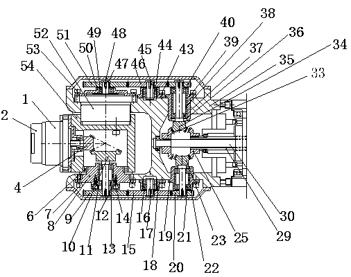
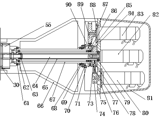
[0036] Such as Figure 2-4 As shown, the upper arm of the robot of the present invention includes a wrist joint power input device and a wrist joint, and the wrist joint power input device includes a fourth joint servo motor 83, a fifth joint servo motor 82, a sixth joint servo motor 80 and a motor protection cover 81 The wrist joint includes the fourth joint reducer 55, the fifth joint reducer 52, the sixth joint reducer 1, the fourth joint power shaft 67, the fifth joint power shaft 64, the sixth joint power shaft 65, the fourth joint power shaft The joint rotating arm 35 , the fifth joint swing arm 54 and the end mechanical flange 2 , the fifth joint power shaft 64 is set in the sixth joint power shaft 65 , and the sixth joint power shaft 65 is set in the fourth joint power shaft 67 . This structure solves the input power distribution problem of the fourth, fifth and sixth joints at the end of the industrial robot.

[0037] In the wrist power input device:

[0038] The ou...


PUM


Abstract

The invention discloses an upper arm of a robot. The upper arm comprises a wrist joint power input device and a wrist joint. The wrist joint power input device comprises a fourth joint servo motor, a fifth joint servo motor, a sixth joint servo motor, and a motor protection cover. The wrist joint comprises a fourth joint reducer, a fifth joint reducer, a sixth joint reducer, a fourth joint power shaft, a fifth joint power shaft, a sixth joint power shaft, a fourth joint rotation arm, a fifth joint rotation arm and a tail-end mechanical flange. The fifth joint power shaft is arranged in the sixth joint power shaft, and the sixth joint power shaft is arranged in the fourth joint power shaft. The upper arm of the robot is compact in structure, easy to assemble, high in transmission efficiency, adjustable in gear clearance, small in overall volume of wrists of the industrial robot, flexible and portable; the fifth and sixth joints are same in modulus optimization, part specifications can be reduced, butch production can be facilitated, and the problems about dispersion of power distribution and routing of servo motor cables in an original structure can be solved.

Description

technical field [0001] The invention relates to a robot upper arm and belongs to the technical field of robots. Background technique [0002] The wrist joint is an important part of the interconnection between the robot arm and the manipulator. Its main function is to adjust and change the position and three-dimensional posture of the manipulator in three-dimensional space. Therefore, the flexibility of the wrist joint in space movement and movement in space The range directly affects the overall function and performance of the robot at work. [0003] At present, the upper arm structure of industrial robots is as follows: figure 1 As shown, the existing industrial robot upper arm includes a third joint swing arm 101, a fourth joint servo motor 102, a fourth joint reducer 103, a fourth joint rotating arm 104, a fifth joint servo motor 105, a sixth joint servo motor 106 , synchronous belt 107 , fifth joint swing arm 108 , sixth joint 109 , fifth joint speed reducer 110 and s...

Claims


Application Information

Patent Timeline
IPC IPC(8): B25J18/00B25J9/08
Inventor 王华英
Owner 成都三译智能技术有限公司
Learn More