Rotary evaporator

An evaporator and rotary technology, applied in the field of rotary evaporators, can solve problems such as cracking, difficulty in replacing and reinstalling evaporating vessels, fragile evaporating vessels, etc., and achieve the effect of simple structure

Active Publication Date: 2014-06-25
KNF NEUBERGER
View PDF5 Cites 14 Cited by
  • Summary
  • Abstract
  • Description
  • Claims
  • Application Information

AI Technical Summary

Problems solved by technology

There is a danger here that the glass assembly fastened to the holder and also containing the evaporator vessel falls towards the stop, so that the fragile evaporator vessel which is still in vacuum can burst
The laborious pivotability of the holder provided on known rotary evaporators makes it difficult to change the evaporator vessel and to replace it with a larger or smaller evaporator vessel, which may also necessitate changing the pivoting angle
Making changing over to a larger or smaller evaporator even more difficult is that the changing evaporator vessel must also be well immersed in the heat bath located in the tempering vessel of the rotary evaporator, which can only be achieved by changing the lift Height and pivot angle to account for different sizes of different evaporator vessels

Method used


Image

  • Rotary evaporator
  • Rotary evaporator
  • Rotary evaporator

Examples


Embodiment Construction

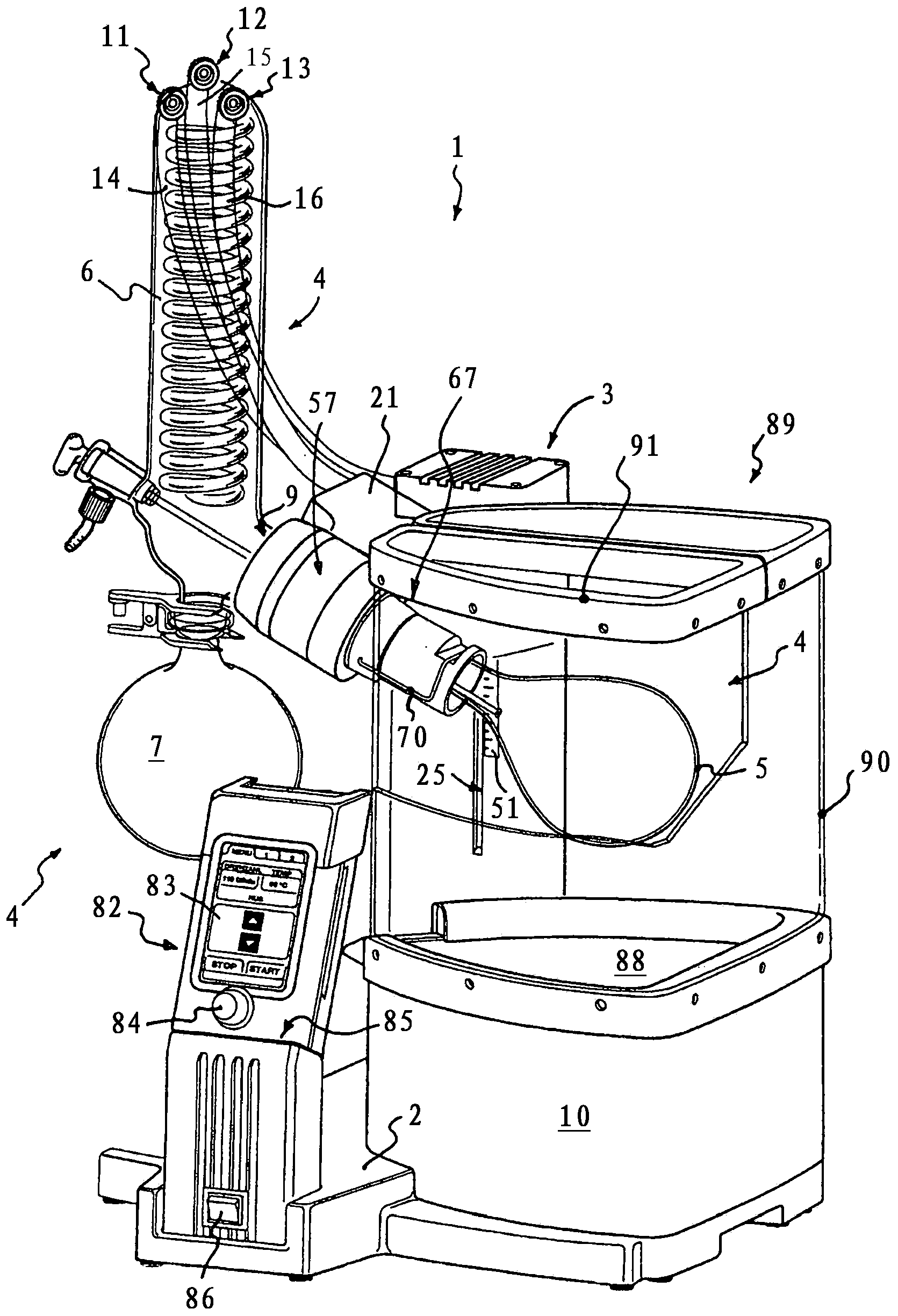
[0028] exist figure 1 shows a rotary evaporator 1 in a perspective view. The rotary evaporator 1 has an instrument base 2 that supports the structure of the rotary evaporator. A guide tower 3 with a vertically directed longitudinal axis protrudes from the instrument base 2 . The rotary evaporator 1 has a glass unit 4 with an evaporator vessel 5 designed here as an evaporator flask, a cooler 6 and a collection vessel 7 detachably connected to the cooler 6 . Here the evaporator vessel 5 is held as a vapor guiding device and in the Image 6 , 7 In the case of the glass hollow shaft 8 further shown in and 9 , the shaft end of the glass hollow shaft facing away from the evaporator vessel 5 leads into the connection pipe 9 of the cooler 6 .

[0029] The rotary evaporator 1 has a tempering vessel 10 , here designed as a heat bath, into which the evaporator vessel 5 is partially immersed. In order to be able to position subregions of the evaporator vessel 5 in the tempering vesse...


PUM


Abstract

The invention relates to a rotary evaporator (1), comprising an equipment stand (2) with a protruding guide tower (3) which has a mounting on which an evaporation tank (5) is pivotably retained about a horizontal pivoting axis (42). In one embodiment of the invention, the mounting comprises a holding part connected to the guide tower, wherein a supporting part (43) that can be connected to the evaporation tank (5) is pivotably retained about a horizontal pivoting axis on the holding part, and a spindle drive (44) is provided for adjusting and determining the selected pivoting position, said spindle drive comprising an adjustment spindle (45) with a self-locking spindle thread (46).

Description

technical field [0001] The invention relates to a rotary evaporator. Background technique [0002] Rotary evaporators are already known in various embodiments. Such rotary evaporators are used to economically separate liquid mixtures and solutions by taking advantage of the different boiling points of the components. In this way the rotary evaporator can also be used for drying, for solvent recovery and similar processes. Usually a thermal bath is used as the evaporator element, in which the heated water or oil volume is located. The evaporator flask, which contains the solution to be evaporated inside its flask, is rotated in a heated volume of water or oil in a thermal bath. The solution is distributed as a thin liquid film on the heated inner wall of the rotary evaporator flask, where it can be easily vaporized. By rotating the evaporator flask, distillation delays are also avoided and, in conjunction with the heating bath, a homogeneous temperature distribution of th...

Claims


Application Information

Patent Timeline
Patent Type & Authority Applications(China)
IPC IPC(8): B01D3/08B01L9/04F16M11/00
CPCF16M2200/048F16M11/24F16M11/105F16M2200/021B01L9/04F16M11/18B01D1/228B01D3/085F16M11/425
Inventor E·豪泽E·贝克尔
Owner KNF NEUBERGER
Why Eureka
Try Eureka