


Quick Research
Generate reliable direction feasibility study reports for your R&D in just a few steps.

Technical Q&A
Discover and master advanced knowledge NOW. Basics, ideas, possibilities, all at once.

Find Solutions
As an expert in R&D theories, this can generate solutions to your technical problems instantly.

Evaluate Feasibility
Analyze your overall solution with one click, know your potential R&D risks in advance.

Monitor Landscape
Get weekly tech updates, stay abreast of the latest tech innovations and key insights.
Electric remote control risk-avoiding and anti-theft device
An anti-theft device and electric technology, applied in the direction of blinds/movable grille, can solve the problems of mass death and mass injury, no function of avoiding danger, and inability to leave the room, so as to prolong the service life, improve the comfort, and ensure normal operation. effect of work
- Summary
- Abstract
- Description
- Claims
- Application Information
AI Technical Summary
Problems solved by technology
Method used
Image

Examples
Embodiment 1
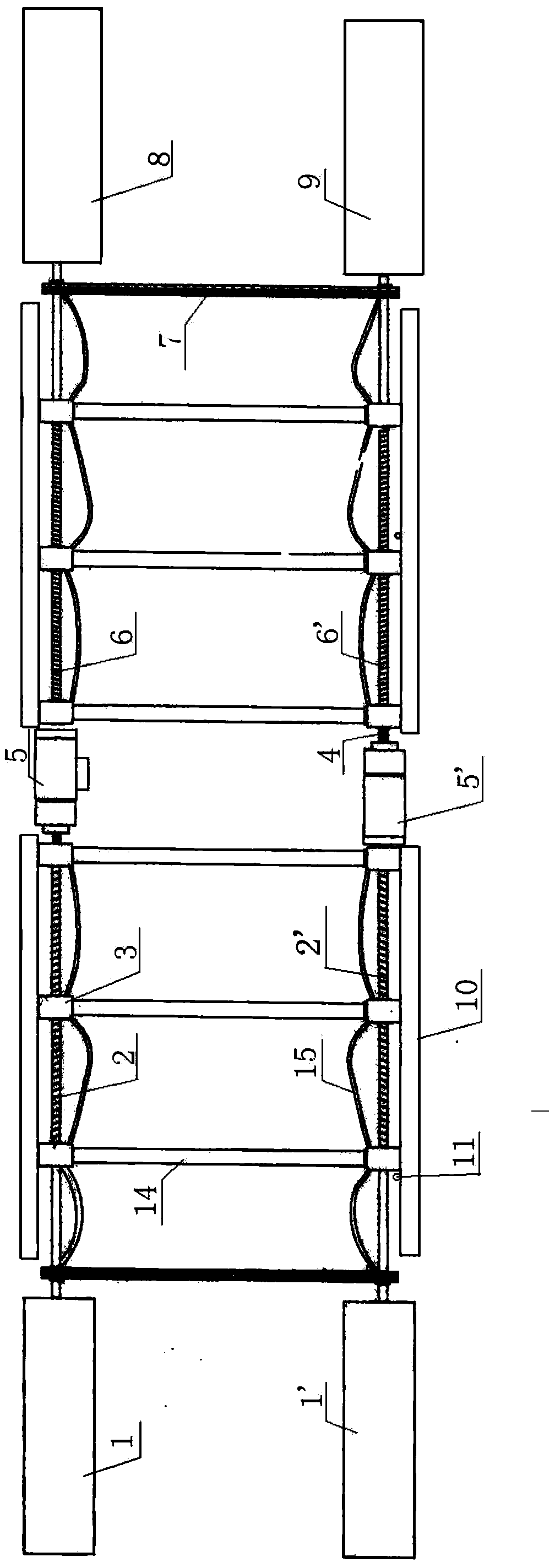
[0028] Such as figure 1 As shown, the electric remote control safety avoidance and anti-theft device includes a housing 16 and a screw drive mechanism. The screw transmission mechanism is composed of left and right parts. The left screw transmission mechanism includes the upper active screw 2 fixedly connected with the upper active beam 1, the lower passive screw 2' fixedly connected with the lower passive beam 1', the upper active screw The rod 2 is arranged symmetrically with the lower passive lead screw 2'. One end of the upper active screw 2 is connected to the upper active beam 1, and the upper active screw 2 is a non-wire section near the upper active beam 1, and the other end of the upper active screw 2 is fixed to the output end of the upper motor 5 through the coupling 4 Connection; one end of the lower passive screw 2' is connected to the lower passive beam 1', and the lower passive screw 2' close to the lower passive beam 1' is a non-wire segment. The upper active...
Embodiment 2
[0039] The difference from Embodiment 1 is that the left and right lead screw transmission mechanisms share one motor, that is, the lower lead screws of the left and right two lead screw transmission mechanisms are all active lead screws, and the upper lead screws are both passive lead screws, and the output of the motor The end is connected to the lower left active lead screw through a transmission mechanism such as a sprocket drive mechanism, and the output end of the motor is connected to the lower right active lead screw through a transmission mechanism such as a sprocket drive mechanism, realizing the left lead screw drive mechanism and the right lead screw drive mechanism Simultaneously complete the opening and closing action.
[0040] It should be noted that the screw threads on the lower left active screw and the lower right active screw must be opposite in direction of rotation, so that the simultaneous opening and closing of the left and right screw transmission mecha...
Embodiment 3
[0043] The difference from Embodiment 1 is: the output end of the upper motor is connected with the upper active lead screw through the transmission mechanism, and at the same time the output end of the upper motor is connected with the upper passive lead screw through the transmission mechanism; the output end of the lower motor is connected with the lower passive lead screw through the transmission mechanism. The lead screw is connected, and the output end of the lower electrode is connected with the lower active lead screw through the transmission mechanism at the same time. The upper motor and the lower motor are synchronous motors, and there is no need to arrange a chain transmission mechanism between the upper active lead screw and the lower passive lead screw, and between the upper passive lead screw and the lower active lead screw. Simultaneously, when selecting the direction of rotation of the output ends of the two motors and the direction of rotation of the left and ...
PUM
 Abstract
Description
Claims
Application Information
 - R&D Engineer
- R&D Manager
- IP Professional
- Industry Leading Data Capabilities
- Powerful AI technology
- Patent DNA Extraction
Browse by: Latest US Patents, China's latest patents, Technical Efficacy Thesaurus, Application Domain, Technology Topic, Popular Technical Reports.
© 2024 PatSnap. All rights reserved.Legal|Privacy policy|Modern Slavery Act Transparency Statement|Sitemap|About US| Contact US: help@patsnap.com