
Emergency shutdown system of gas cut-off valve

A technology for shutting down systems and shut-off valves, applied to blast furnace parts, furnaces, heating furnaces, etc., can solve problems such as gas leakage, inability to realize remote closing of gas shut-off valves, accidents, etc.

Active Publication Date: 2014-06-25
JIGANG GRP
View PDF4 Cites 5 Cited by
  • Summary
  • Abstract
  • Description
  • Claims
  • Application Information

AI Technical Summary

Problems solved by technology

[0003] When the hot blast stove is in normal production, the operating system of the hot blast stove is two firings and one delivery, that is, two hot blast stoves are in the state of burning, one hot blast stove is in the state of supplying air to the blast furnace, and the gas shut-off valve of the hot blast stove that is burning the furnace is open. The gas cut-off valve of the hot blast stove that is supplying air is closed. During the normal production process of the hot blast stove, if a large-scale power failure occurs suddenly in the power supply system of the hot blast stove, the air combustion fan will stop immediately, and the air will immediately stop entering the hot blast stove. The pressure will not drop immediately, and the gas will continue to enter the hot blast stove. If the gas entering the hot blast stove cannot be quickly cut off in a short period of time, that is, the gas cut-off valve of the hot blast stove that is in the air supply is not closed in time, which will cause huge production. Safety accidents, if serious, will cause gas leakage and blast stove explosion, resulting in equipment damage and casualties, and due to the occurrence of large-scale power failures in the power supply system, the normal power supply of the gas shut-off valve is interrupted, and the remote closing of the gas shut-off valve cannot be realized. However, relying on manual operation to close the gas shut-off valve cannot cut off the gas immediately, and it will still cause production safety accidents. It can be seen that in the gas shut-off valve control system, there is a need for a system that can quickly shut off the gas in the event of a large-scale power failure. The emergency device of the cut-off valve cuts off the input of gas into the hot blast stove to realize the protection of equipment and personnel

Method used


Image

  • Emergency shutdown system of gas cut-off valve
  • Emergency shutdown system of gas cut-off valve

Examples


Embodiment Construction

[0015] In order to clearly illustrate the technical features of the solution, the solution will be described below through a specific implementation mode combined with the accompanying drawings.

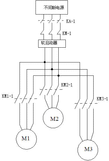
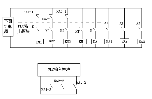
[0016] It can be seen from the accompanying drawings that an emergency closing system for a gas shut-off valve of this program includes an uninterruptible power supply, and the uninterruptible power supply is connected to the gas shut-off valve through a soft starter, and has a switch input module and a switch The PLC controller of the output module has three valve emergency switches K1, K2, K3, which correspond to three gas cut-off valves M1, M2, M3 respectively, and are used to control the gas of the three hot blast stoves.

[0017] The first valve emergency switch K1 and the first emergency cut-off relay KM1 are connected in series to the uninterruptible power supply. The normally open contact KM1-1 of the first emergency cut-off relay is connected in series with the first gas cut-...


PUM


Abstract

The invention provides a technical scheme of an emergency shutdown system of a gas cut-off valve. The emergency shutdown system of the gas cut-off valve is of a combined structure consisting of an uninterruptible power supply, a soft starter and a relay control element so as to reach a purpose of driving an inductive load by using the uninterruptible power supply; the emergency shutdown system of the gas cut-off valve is simple in structure, convenient to maintain, and accurate and reliable; in the case of a large-area power cut fault of a hot blast furnace power supply system, the emergency shutdown system of the gas cut-off valve is capable of shutting down the gas cut-off valve quickly, stopping supply of gas to the hot blast furnace, preventing gas leakage and hot blast furnace explosion and protecting equipment and staff.

Description

technical field [0001] The invention relates to a device for emergency closing of a gas cut-off valve during the ironmaking production process of a blast furnace. Background technique [0002] During the blast furnace ironmaking production process, a large amount of blast furnace gas is produced, and the blast furnace gas is sent into the gas main pipe through pipelines for use in other production processes using blast furnace gas. Under normal circumstances, each blast furnace is equipped with 3 hot blast stoves. The hot blast stove generates hot air by mixing blast furnace gas and air in the vault to supply the blast furnace. When the hot blast stove burns in the vault, the gas and air respectively pass through the gas shut-off valve and air The cut-off valve enters the dome combustion chamber for combustion to generate hot air. [0003] When the hot blast stove is in normal production, the operating system of the hot blast stove is two firings and one delivery, that is, ...

Claims


Application Information

Patent Timeline
IPC IPC(8): C21B7/00C21B9/10
Inventor 夏江波袁望浪郝之峰戚大波付延亮王军冯会玉金立坤陈健孔凡强
Owner JIGANG GRP
Learn More