
Pneumatic control system in elevator lift car

An elevator car and air pressure control technology, which is applied to elevators, elevators, transportation and packaging in buildings, etc., can solve problems such as changes in the atmospheric pressure of the car, the size of the blower is not clearly indicated, and the rapid change of air pressure cannot be achieved. Structure, the effect of prolonging the service life

Inactive Publication Date: 2014-06-25
TONGJI UNIV
View PDF7 Cites 11 Cited by
  • Summary
  • Abstract
  • Description
  • Claims
  • Application Information

AI Technical Summary

Problems solved by technology

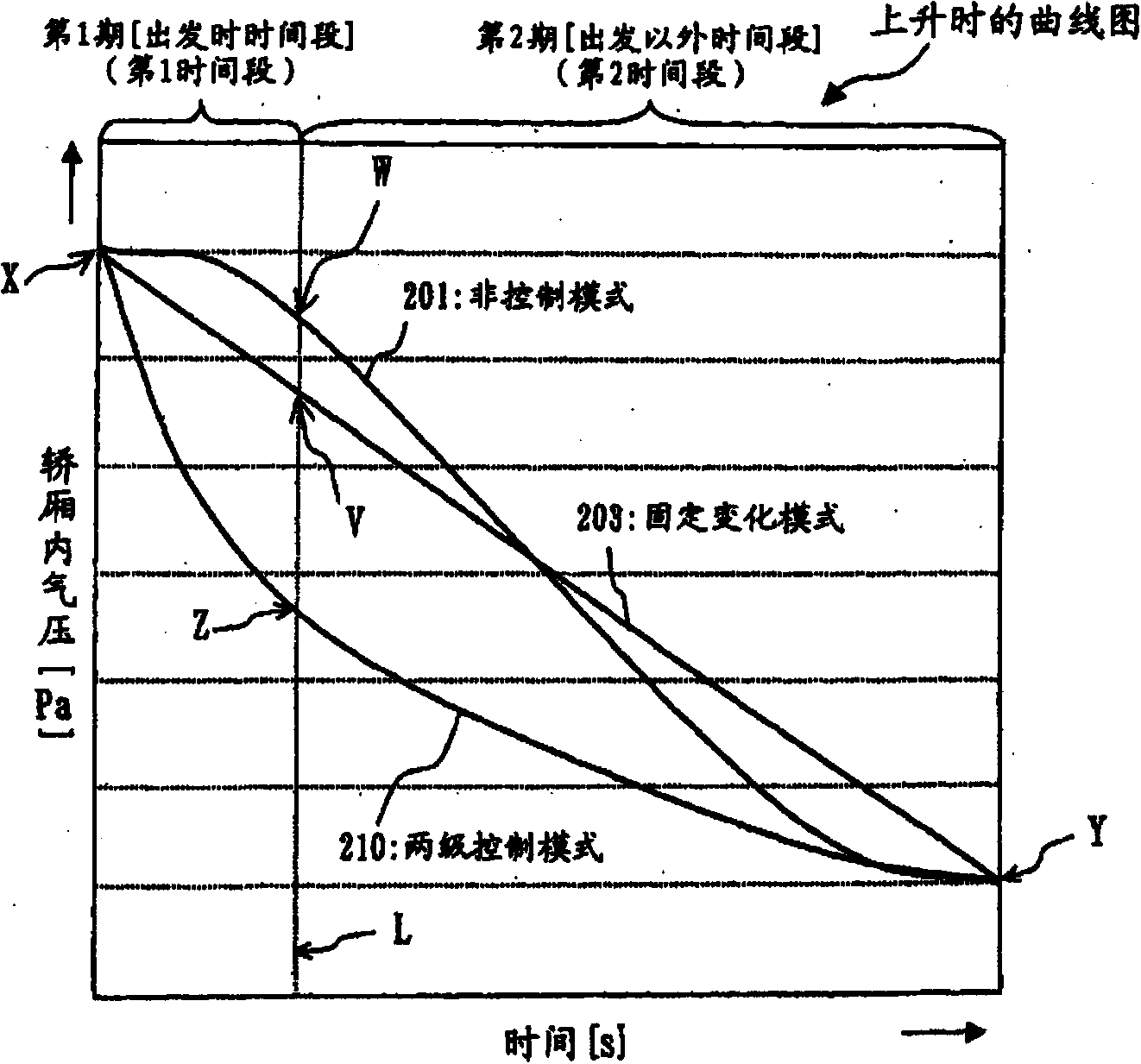
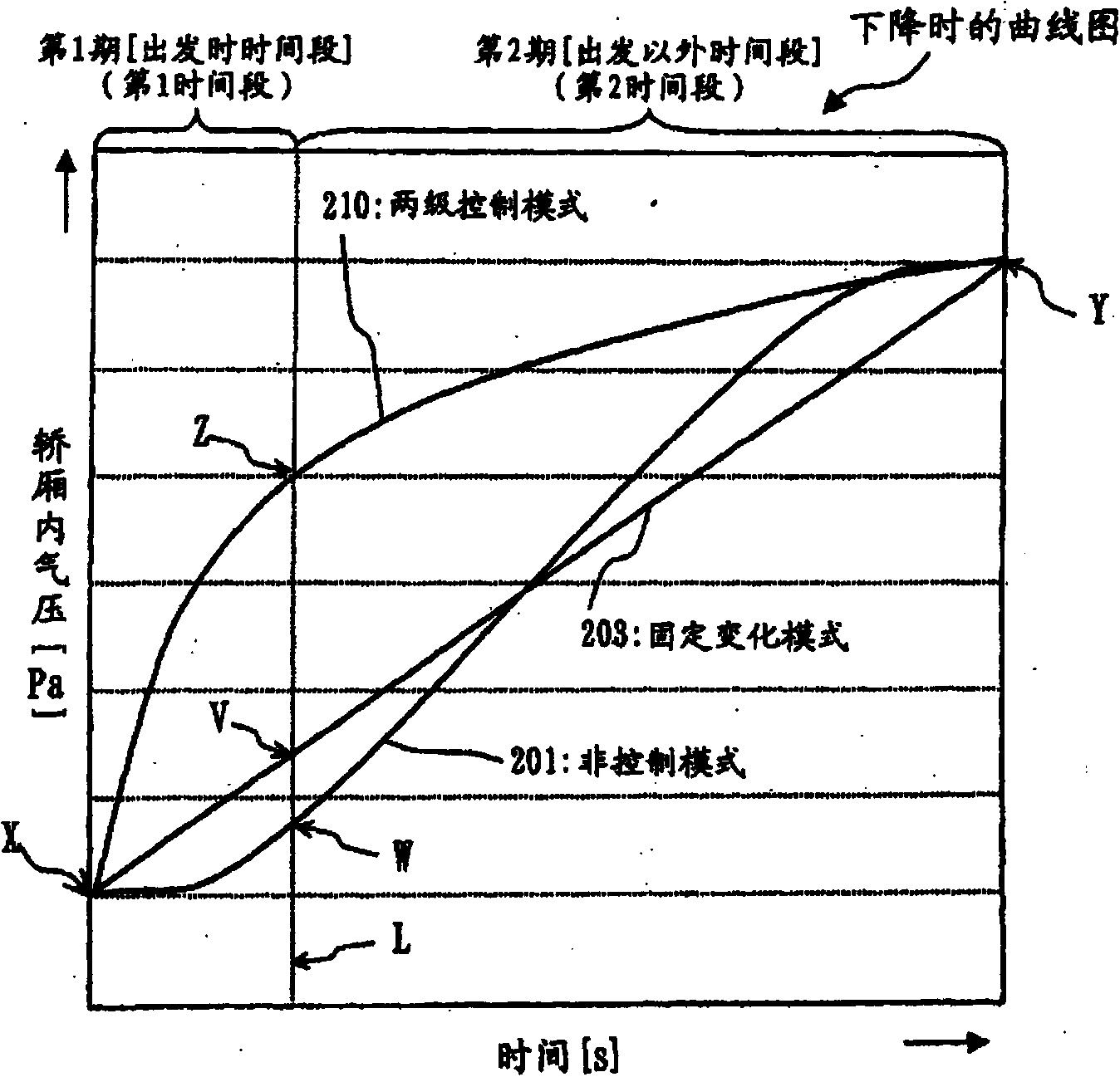
In the above-mentioned long-travel ultra-high-speed elevator, there is the following problem: as the elevator car moves up and down, a large air pressure fluctuation will occur in the car
However, in the prior art, the size of the blower is not clearly indicated. Since the blower is limited by the size of the elevator car and the allowable noise of the elevator, it is impossible to use a blower with a large wind power.
Therefore, it can be considered that only a blower with small wind power cannot meet the requirements of rapid changes in the air pressure in the elevator car.

Method used


Image

  • Pneumatic control system in elevator lift car
  • Pneumatic control system in elevator lift car
  • Pneumatic control system in elevator lift car

Examples


Embodiment 1

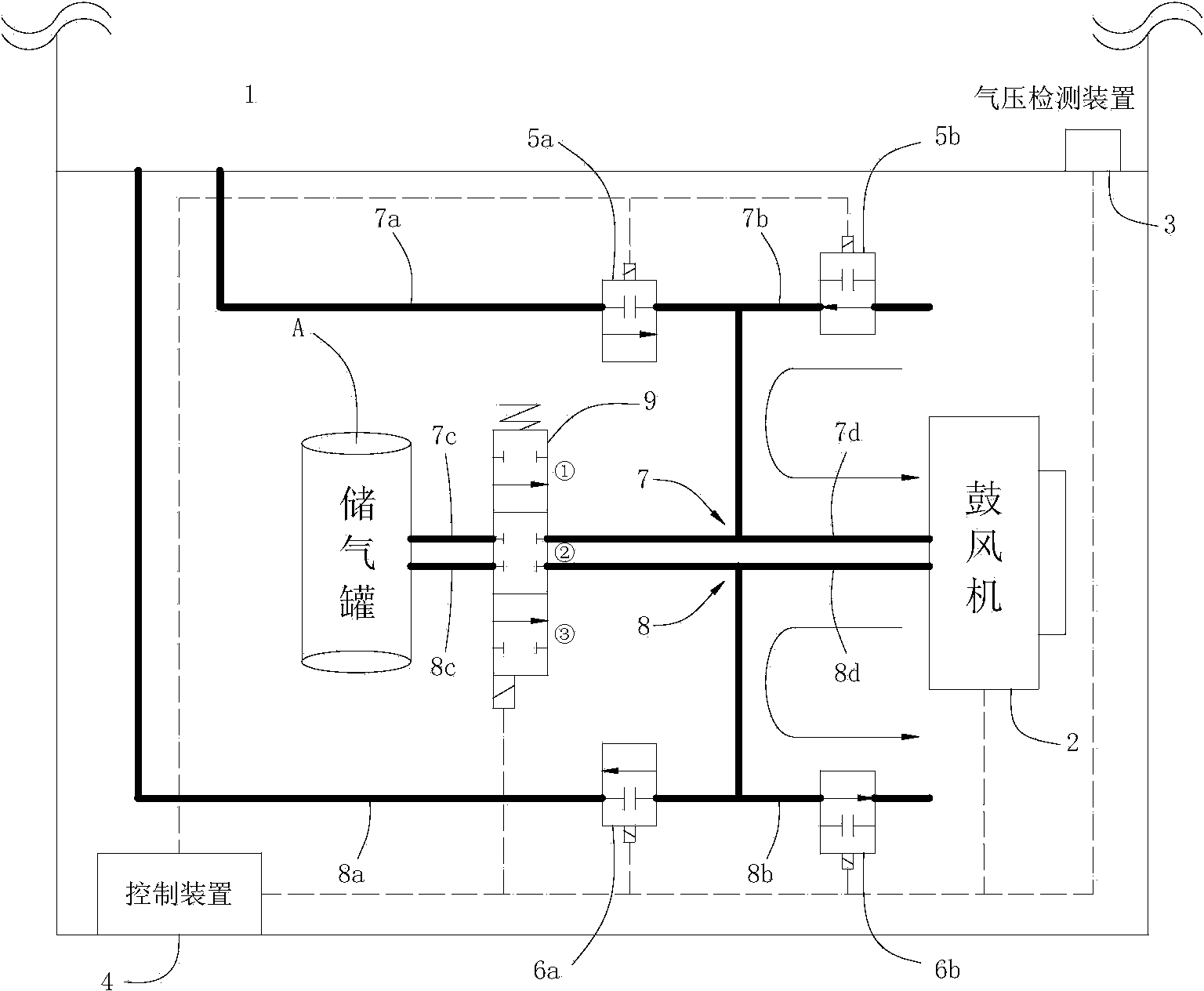
[0060] Figure 3 to Figure 9 Embodiment 1 of the air pressure control system in an elevator car according to the present invention is shown.

[0061] Such as Figure 3 to Figure 9 As shown, the air pressure control system in the elevator car of the present embodiment for controlling the air pressure in the elevator car 1 is arranged at the bottom of the elevator car 1, and the system has: a blower 2 with a small wind force, which is arranged The bottom of the elevator car 1, and continuously generates wind pressure in one direction when the elevator is running; an air storage tank A, whose function is to discharge the air in the elevator car 1 and reduce the air pressure in the elevator car 1 , or used to fill air into the elevator car 1 to increase the air pressure in the elevator car 1; a three-position four-way reversing valve 9, the reversing valve controls its position through the control device 4; decompression Use the piping group 7, which has a first decompression pi...

Embodiment approach 2

[0084] Such as Figure 12 to Figure 19 As shown, the air pressure control system in the elevator car of the present embodiment for controlling the air pressure in the elevator car 1 is arranged at the bottom of the elevator car 1. Wind pressure is continuously generated in one direction during operation; two air storage tanks (B, C), one of the two air storage tanks is the air storage tank B used to discharge the air in the elevator car 1, which can reduce The effect of the air pressure in the elevator car 1, the other of the two air storage tanks is the air storage tank C used to fill the elevator car 1 with air, which plays the role of increasing the air pressure in the elevator car 1; The pressure piping group 7 has a fifth decompression piping 7e, one end of which is open in the elevator car 1, the other end connected to one end of the decompression air tank B, and a second decompression piping 7e, one end of which is open to the atmosphere. The piping 7b, and the sixth d...


PUM


Abstract

The invention relates to a pneumatic control system in an elevator lift car. An elevator is controlled to reduce pressure in the elevator lift car in the ascending process or to increase pressure in the elevator lift car in the descending process. The pneumatic control system comprises an air blower, an air storage tank, a pressure reduction piping group, a pressure increase piping group, a valve set, an air pressure detecting device and a control device. The air blower is arranged at the bottom of the elevator lift car, air pressure is generated continuously in the same direction when the elevator operates, and air is filled into the air storage tank or exhausted from the air storage tank so that positive pressure or negative pressure can be formed. The pressure reduction piping group and the pressure increase piping group are connected with the elevator lift car, the air blower and the air storage tank. The valve set is arranged in the pressure reduction piping group and the pressure increase piping group for controlling air circulation. The air pressure detecting device detects the air pressure in the elevator lift car and outputs detection signals. The control device regulates the opening and closing and the opening size or the opening position of the valve set according to the detection signals and controls the air pressure in the elevator lift car. Compared with the prior art, the pneumatic control system in the elevator lift car can eliminate the discomfort of passengers due to ear pressure in the ultra high-speed elevator lift car in the lifting process.

Description

technical field [0001] The invention relates to an air pressure control system, in particular to an air pressure control system in an elevator car. Background technique [0002] In recent years, with the continuous emergence of super high-rise buildings, the lifting speed of elevators has also been continuously improved. Today's fastest ultra-high-speed elevator is close to 18m / s, and the maximum travel distance is more than 500 meters. In the above-mentioned long-travel ultra-high-speed elevator, there is a problem that a large air pressure fluctuation occurs in the car as the elevator car moves up and down. Such air pressure fluctuations will cause uncomfortable ear pressure to the passengers in the car. In severe cases, it can even cause tinnitus. [0003] As a method to solve this problem, a known method is to set a blower in the elevator to adjust the air pressure in the elevator car through a suction and exhaust air volume adjustment mechanism, such as the technical...

Claims


Application Information

Patent Timeline
Patent Type & Authority Applications(China)
IPC IPC(8): B66B1/06B66B11/02
Inventor 周爱国梅存浩林宝照
Owner TONGJI UNIV
Learn More