High-efficiency energy-saving heating base

A heating base, high-efficiency and energy-saving technology, applied in the direction of heating devices, etc., can solve the problems of energy waste and the inability of the heater to keep warm, and achieve the effect of increasing the heating area, reducing the loss of heat, and increasing the heating time.

Inactive Publication Date: 2014-06-18
刘兵
View PDF7 Cites 0 Cited by
  • Summary
  • Abstract
  • Description
  • Claims
  • Application Information

AI Technical Summary

Problems solved by technology

[0002] The soup buckets on the market are usually heated directly by fuels such as honeycomb coal, liquefied petroleum gas, and natural gas. A smoking machine is added to the flue to discharge the smoke directly, and a large amount of heat is taken away at the same time, resulting in a waste of energy.
At the same time, if fuels such as liquefied gas and natural gas are used for heating, when the soup bucket needs to be kept warm, the fire can only be turned down, and the heater cannot be used to achieve the heat preservation effect.

Method used


Image

  • High-efficiency energy-saving heating base
  • High-efficiency energy-saving heating base
  • High-efficiency energy-saving heating base

Examples


Embodiment 1

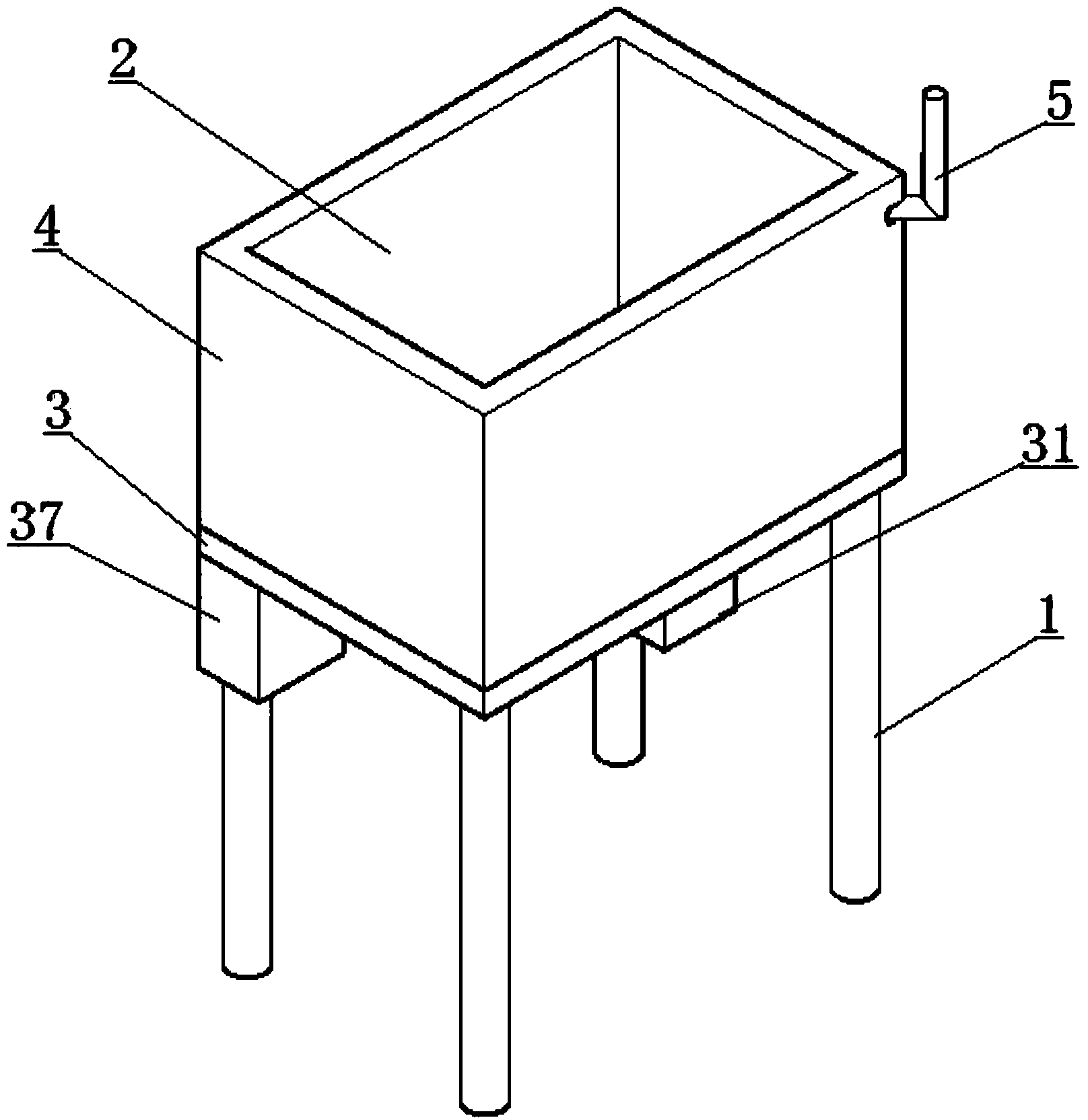
[0026] Such as figure 1 The high-efficiency and energy-saving heating base shown includes a support 1, a heat preservation seat 2 and a smoke exhaust pipe 5. The heat preservation seat 2 is installed on the support 1, and the smoke exhaust pipe 5 is fixed on the heat preservation seat 2. The heat preservation seat 2 includes the bottom of the seat body 3 and side walls 4,

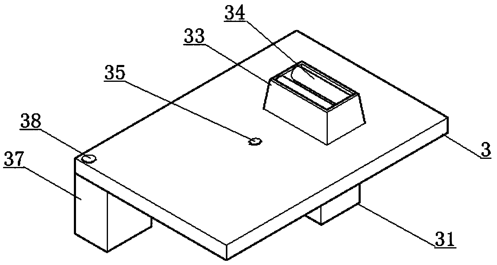
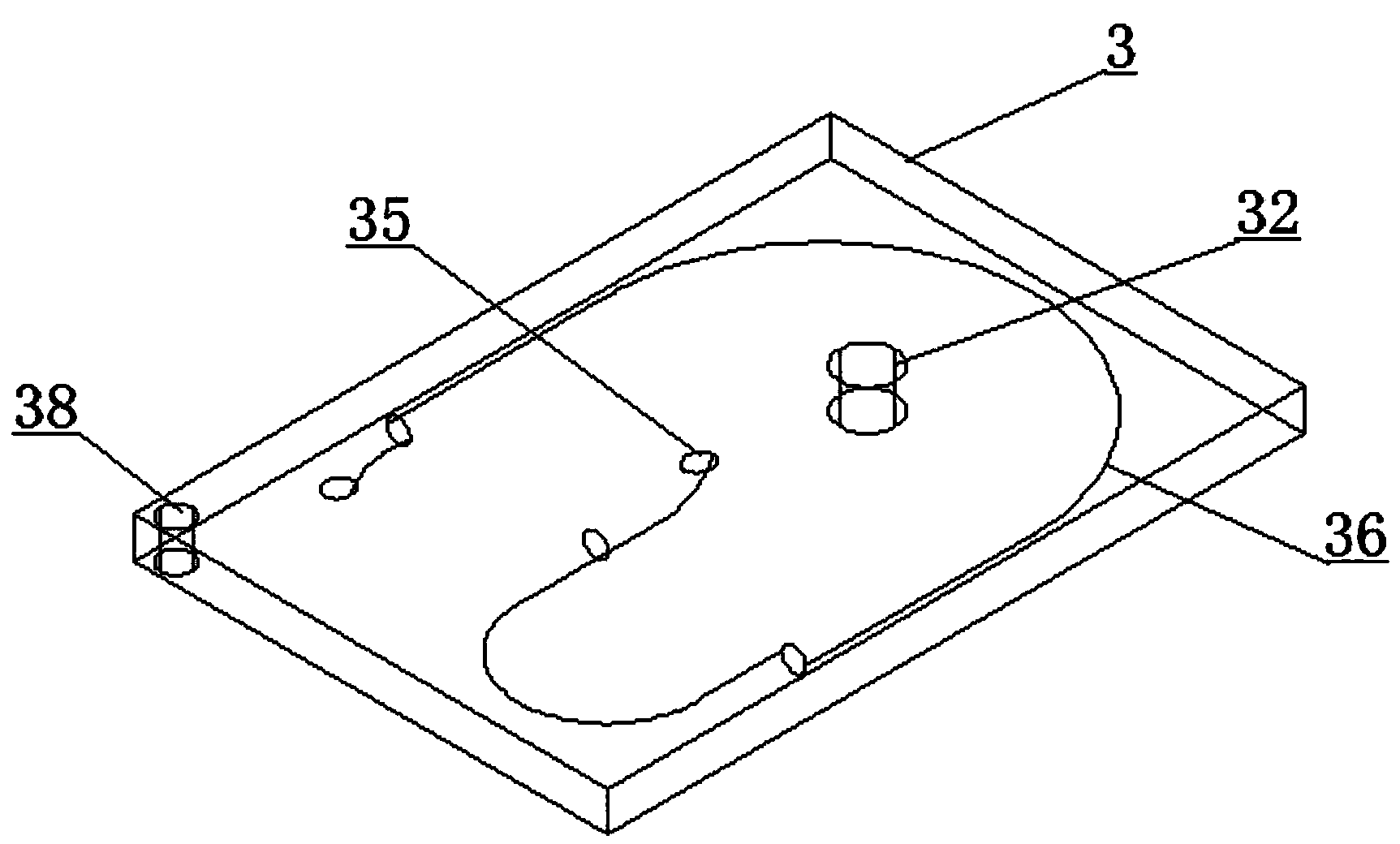
[0027] Such as Figure 2~3 Shown is a schematic diagram of the bottom 3 of the high-efficiency energy-saving heating base heat preservation seat 2. The bottom 3 of the base includes a burner 31, a furnace mouth 32, a heat receiver 33, a smoke inlet 35, a bottom flue 36, a smoking machine 37 and a bottom smoke outlet. Port 38, wherein burner head 31 and heat receiver 33 are respectively connected to the upper and lower sides of base body bottom 3, and the centers of burner head 31 and heat receiver 33 are on the same vertical line as the center of burner mouth 32; smoke inlet 35 is at the base body bottom ...

Embodiment 2

[0031] In order to increase the absorption conversion rate of the side wall 4 to the heat energy of the hot smoke in the side wall flue 41, the connection of the bottom smoke outlet 38 on the side wall 4 and the connection of the smoke exhaust pipe 5 on the side wall 4 are located at On the two opposite corners of the side wall 4, the side wall flues 41 can be 2, 4, 6, etc., which are respectively connected to the smoke exhaust port 38 and the smoke exhaust pipe 5, and the side wall flues 41 are on the side 4 Each side can be straight or curved.

Embodiment 3

[0033] In order to reduce soot remaining in the heat preservation flue, the heat preservation pipe 41 inside the side wall 4 forms an angle of 40° with the horizontal plane. Other structures are the same as in Embodiment 1.


PUM


Abstract

The invention discloses a high-efficiency energy-saving heating base. The high-efficiency energy-saving heating base comprises a support, a heat-preserving seat and a smoke exhaust pipe, wherein the heat-preserving seat comprises a seat bottom and a side wall, the seat bottom comprises a furnace end, a furnace mouth, a heated device, a smoke inlet, a bottom flue, a smoke sucker and a bottom smoke outlet, the furnace end and the heated device are respectively connected to the upper surface and the lower surface of the seat bottom in the furnace mouth; the smoke inlet is arranged in the center of the seat bottom, and the smoke sucker is fixed on one corner of the lower side surface of the seat bottom; a disc-shaped smoke pipe is arranged in the seat bottom and respectively connected with the smoke inlet and the smoke sucker; the bottom smoke outlet is communicated with the smoke sucker; a side wall flue is arranged in the side wall, and the side wall flue is respectively connected with the bottom smoke outlet and the smoke exhaust pipeline. By designing the heated device, the bottom flue and the heat-preserving flue in the heat-preserving seat, the heated area and the heated time of the heat-preserving seat can be increased, the absorbed heat is maximized; meanwhile, the heat-preserving seat is provided with a heat-preserving layer, so that the loss of the heat is reduced, and an energy-saving effect is realized.

Description

technical field [0001] The invention relates to a heater, in particular to a high-efficiency and energy-saving heating base. Background technique [0002] The soup buckets on the market are usually heated directly by fuels such as honeycomb coal, liquefied petroleum gas, and natural gas. A smoking machine is added to the flue to discharge the smoke directly, and a large amount of heat is taken away at the same time, resulting in a waste of energy. Simultaneously as when using fuels such as liquefied petroleum gas and natural gas to heat, when the soup bucket needs to be kept warm, the fire can only be turned down, and the heater cannot be used to achieve the heat preservation effect. Contents of the invention [0003] Aiming at the above technical problems, the present invention provides a high-efficiency and energy-saving heating base. By improving the internal structure of the heater, the heater can shorten the boiling time of the soup in the soup bucket, and at the same...

Claims


Application Information

Patent Timeline
Patent Type & Authority Applications(China)
IPC IPC(8): A47J36/26
Inventor 刘兵
Owner 刘兵
Why Eureka
Try Eureka