A laser displacement sensor calibration device

A calibration device, laser displacement technology, applied in the direction of using optical devices, measuring devices, instruments, etc., can solve the problem of doubts about the accuracy of measurement results, avoid human measurement errors, improve work efficiency and convenience of use, and improve measurement. The effect of precision

Inactive Publication Date: 2017-01-04
中国兵器工业第二0二研究所
View PDF6 Cites 0 Cited by
  • Summary
  • Abstract
  • Description
  • Claims
  • Application Information

AI Technical Summary

Problems solved by technology

At present, the dynamic measurement of relative displacement of artillery at home and abroad generally adopts the following measurement methods, eddy current displacement sensor, laser vibrometer, steel wire displacement sensor and PSD or CCD laser displacement sensor, etc. When using these sensors to measure, the measurement system The measurement accuracy is generally based on the performance indicators given by the sensor manufacturer, and the calibration of the test site is not carried out. It is only to verify whether the measurement system is working normally, or use a steel ring ruler to measure the distance between the laser reflector and the laser sensor in the laboratory or test site. The distance between the measured distance and the output value of the sensor is used to compare the accuracy of the sensor system. In this way, people will doubt the accuracy of the measurement results, and cause disagreements and disputes between the manufacturer and the acceptance party.

Method used


Image

  • A laser displacement sensor calibration device
  • A laser displacement sensor calibration device

Examples


Embodiment Construction

[0010] The best embodiment of the present invention will be described in detail below with reference to the accompanying drawings.

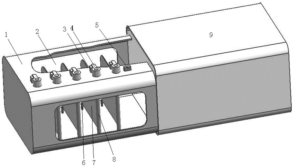
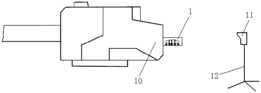
[0011] Such as figure 1 As shown, the laser displacement sensor verification device of the preferred embodiment of the present invention includes: a main body 1, a light transmission port 2, a magnet 3, a conversion button 4, a positioning magnet 5, a positioning stopper 6, a laser reflection plate 7, a rotating shaft 8 and a box Body 9. The main body 1 is made of thin-plate stainless steel with a small deformation coefficient to ensure that the installation position between the rotating shafts 8 where the five laser reflectors 7 are installed does not change with the external environmental conditions. For example, the expansion rate of 3Cr13 is 12%, and the expansion rate of 0Cr26Ni5Mo2 is 18%. The expansion rate of 00Cr18Ni5Mo3Si2 is 20%, and the expansion rate of 0Cr13Al is 20%. The smaller the expansion rate, the smaller the deformation unde...


PUM


Abstract

The invention relates to a laser displacement sensor verifying device which comprises a body, light-transmitting ports, a magnet, switching buttons, a positioning magnet, a positioning stop block, laser reflecting plates, rotating shafts and a box body, wherein the body is made of a stainless steel sheet with low deformation coefficient into a cuboid shape, and the upper surface and lower surface of the body are respectively provided with rectangular light-transmitting ports; the switching buttons are attracted through the magnet or the positioning magnet; the laser reflecting plates are made of white stainless steel sheets, and the surfaces of the laser reflecting plates are designed into non-specular surfaces and connected with the laser rays of the rotating shafts in a welding way; one ends of the rotating shafts are adhered to and fixedly connected with the switching buttons by using adhesives, and the other ends of the rotating shafts are inserted into holes inside the rotating shafts by using screw rods and tightly adhered to the rotating shafts by using the adhesives. According to the laser displacement sensor verifying device, the laser beams of the verified laser displacement sensor are emitted to the central positions of the laser reflecting plates, the switching buttons are respectively pulled from front to back or from back to front according to that the laser beams of the verified laser displacement sensor are emitted to the central position of the laser reflecting plates, a sensor system acquisition system acquires the position data of a plurality of the laser reflecting plates, so that the verification of the laser displacement sensor is completed. The laser displacement sensor verifying device disclosed by the invention is loaded into the box body when being not in use.

Description

technical field [0001] The invention belongs to the technical field of artillery testing, and more specifically relates to a test site calibration and performance testing device for a laser displacement sensor. Background technique [0002] In the test of artillery, there are many dynamic measurements of displacement, such as artillery recoil, comprehensive clearance of turret drive train, azimuth driving amount, artillery trunnion runout, barrel runout, automaton travel, etc. In the process of production, maintenance and performance appraisal, the dynamic measurement of the relative displacement of the artillery is very important and indispensable. At present, the dynamic measurement of relative displacement of artillery at home and abroad generally adopts the following measurement methods, eddy current displacement sensor, laser vibrometer, steel wire displacement sensor and PSD or CCD laser displacement sensor, etc. When using these sensors to measure, the measurement sys...

Claims


Application Information

Patent Timeline
Patent Type & Authority Patents(China)
IPC IPC(8): G01B11/02
Inventor 李宗贤豆征李勇李逢翟鑫赵美丽刘庆国丁良华曹志荣宋巍
Owner 中国兵器工业第二0二研究所
Why Eureka
Try Eureka