
A valve core group switching control mechanism

A control mechanism and spool technology, applied to valve details, multi-way valves, valve devices, etc., can solve problems such as inconvenient use and troublesome operation, and achieve the effect of short operation stroke, small operation force and novel control mode

Active Publication Date: 2016-08-17
JOMOO KITCHEN & BATHROOM
View PDF5 Cites 1 Cited by
  • Summary
  • Abstract
  • Description
  • Claims
  • Application Information

AI Technical Summary

Problems solved by technology

Among them, the push-type spool, as the name suggests, opens and closes its waterway by pressing. The traditional push-type spool mainly realizes operation control by pressing its joystick. When there are multiple push-type spools that need to be switched When the water is discharged, it can only be realized by one-by-one operation. For example, first close the push-type valve core that does not need water discharge, and then open the push-type valve core that requires water discharge, which makes the operation very troublesome and inconvenient to use

Method used


Image

  • A valve core group switching control mechanism
  • A valve core group switching control mechanism
  • A valve core group switching control mechanism

Examples


Embodiment Construction

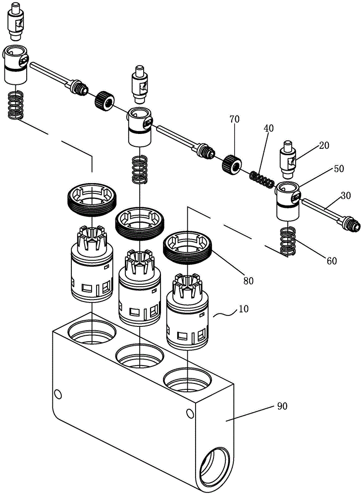
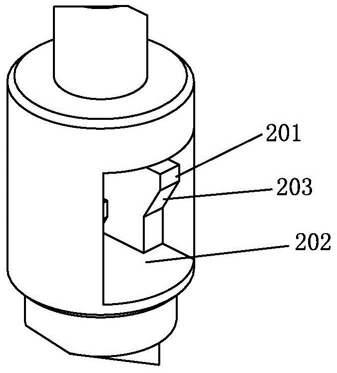
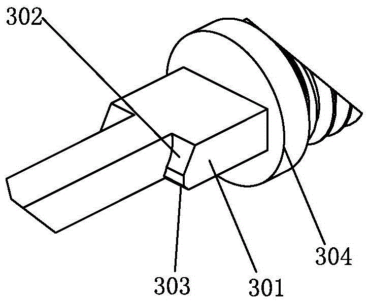
[0030] For the embodiment, please refer to the accompanying drawings, a spool group switching control mechanism of the present invention includes three spools 10 (the spools 10 are push-type spools), and also includes three button modules and a first The elastic member 40, each button module includes a button 20 and a control rod 30 for opening the spool 10, the button 20 is matched with the spool 10, the control rod 30 can move along its axial direction and is assembled on the button 20, and the control rod A locking structure for locking the key 20 is fitted between the key 30 and the key 20 . The control rods of the three button modules are coaxially linked, and one of the control rods is connected with a first elastic member 40 for returning (of course, the three control rods can also be connected to a first elastic member 40 respectively). Among the three buttons 20, two buttons are in the state of returning, and one button is in the state of being pressed. Any button in...


PUM


Abstract

The invention discloses a valve element group switching control mechanism. The valve element group switching control mechanism comprises at least two valve elements and further comprises at least two key modules and a first elastic piece. Each key module comprises a key for opening the corresponding valve element and a control rod, wherein the keys and the valve elements are correspondingly matched; each control rod can be assembled on the corresponding key in a way of being capable of moving along the axial direction of the corresponding key; a locking structure for locking the corresponding key is matched between each control rod and the corresponding key. The control rods of at least two key modules are coaxially linked; the control rod of at least one key module is connected with the first elastic piece for resetting; any one key at a resetting state is used for opening the corresponding valve element in a pressing manner and drives each control rod to do the axial movement; the corresponding control rod is used for driving the corresponding locking structure through resetting to lock the pressed key; the residual control rod is used for driving the corresponding locking structure through axial movement to unlock the corresponding pressed key, so that the key is reset. With the adoption of the structure, the valve element group switching control mechanism can be used for realizing linkage type switching control of at least two valve elements.

Description

technical field [0001] The invention relates to a switching control mechanism, in particular to a valve core group switching control mechanism. Background technique [0002] At present, the spools in the prior art include rotary spools, push spools and the like. Among them, the push-type spool, as the name suggests, opens and closes its waterway by pressing. The traditional push-type spool mainly realizes operation control by pressing its joystick. When there are multiple push-type spools that need to be switched When the water comes out, it can only be realized by one-by-one operation. For example, first close the push-type valve core that does not need water outlet, and then open the push-type valve core that needs water outlet, which makes the operation very troublesome and inconvenient to use. Contents of the invention [0003] The purpose of the present invention is to overcome the shortcomings of the prior art and provide a control mechanism for switching valve core...

Claims


Application Information

Patent Timeline
Patent Type & Authority Patents(China)
IPC IPC(8): F16K11/22
CPCF16K11/22F16K31/44
Inventor 林孝发林孝山梁绍团
Owner JOMOO KITCHEN & BATHROOM
Learn More