
Cutting-to-length system and cutting-to-length method

A technology of fixed-length shearing and conveying roller table, which is applied in the field of shearing system, can solve the problems of insufficient shearing of the tail of steel, high labor intensity of workers, time-consuming and labor-intensive problems, etc., and achieves simple structure, simple construction, and increased mechanism or maintenance. Effect

Active Publication Date: 2014-06-11
LAIWU IRON & STEEL GRP
View PDF9 Cites 6 Cited by
  • Summary
  • Abstract
  • Description
  • Claims
  • Application Information

AI Technical Summary

Problems solved by technology

As a result, the tail of part of the steel is lower than the cutting edge of the lower cutting edge. At this time, it is necessary to manually lift the tail of the steel and slide it to the lower cutting edge to place it on the cutting edge of the lower cutting edge. In order to realize the cutting of the tail of the steel, the labor intensity of the workers is high, and it is time-consuming and laborious.
[0005] Therefore, how to realize the flatness of the steel tail when cutting the steel tail, and avoid the problem of insufficient or excessive shearing of the steel tail has become a technical problem urgently to be solved by those skilled in the art

Method used


Image

  • Cutting-to-length system and cutting-to-length method
  • Cutting-to-length system and cutting-to-length method
  • Cutting-to-length system and cutting-to-length method

Examples


Embodiment Construction

[0045] The core of the present invention is to provide a cut-to-length system to achieve the leveling of the tail of the steel when cutting the tail of the steel and avoid the problem of insufficient or excessive cutting of the tail of the steel.

[0046] The following will clearly and completely describe the technical solutions in the embodiments of the present invention with reference to the accompanying drawings in the embodiments of the present invention. Obviously, the described embodiments are only some, not all, embodiments of the present invention. Based on the embodiments of the present invention, all other embodiments obtained by persons of ordinary skill in the art without making creative efforts belong to the protection scope of the present invention.

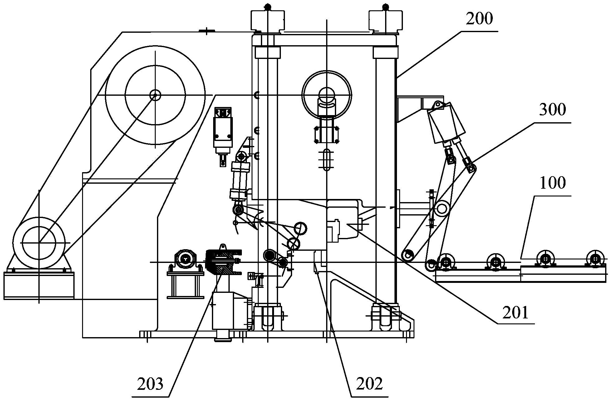
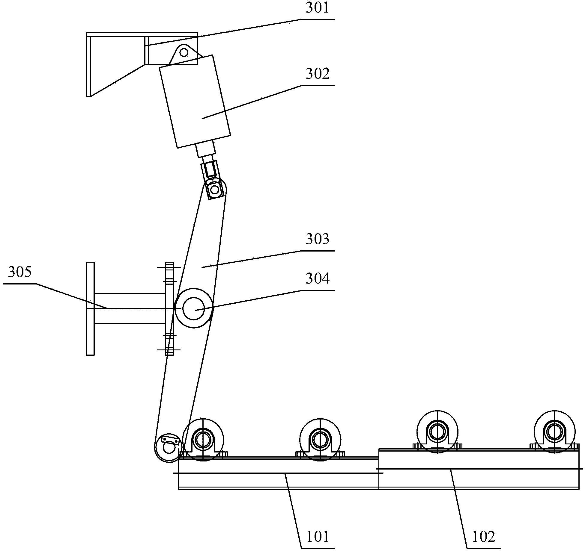
[0047] see figure 2 and image 3 , figure 2 Structural schematic diagram of the cut-to-length system provided for the embodiment of the present invention; image 3 It is a schematic structural diagram of the co...


PUM


Abstract

The invention discloses a cutting-to-length system and a cutting-to-length method. The cutting-to-length system comprises a cold shear and conveying roller ways which are arranged at one side of an outlet of the cold shear, wherein the conveying roller ways comprise a first conveying roller way and a second conveying roller way which are arranged from one side close to the cold shear to the other side, the conveying height of the first conveying roller way is lower than that of the second conveying roller way, and the conveying height of the second conveying roller way is the same as the height of a lower shear blade of the cold shear. According to the cutting-to-length system disclosed by the invention, the alignment of tail parts of steel materials can be realized by directly utilizing the end surface of the lower shear blade, the aligned tail parts of the steel materials are lifted and are higher than a blade opening of the lower shear blade, the tail parts of the steel materials can be placed by getting back to the upper part of the blade opening of the lower shear blade through matching with the reverse rotating of the conveying roller way, and the problem during re-cutting that the tail parts of the steel materials are not cut enough or the cutting is excessive can be avoided; the improvement of the conveying roller ways does not need civil construction, only a groove steel of a conveying roller way base needs to be replaced, the construction is simple and quick, the alignment of the tail parts of the steel materials is realized by utilizing the lower shear blade, the structure is simple, and mechanisms or maintenance amount cannot be added.

Description

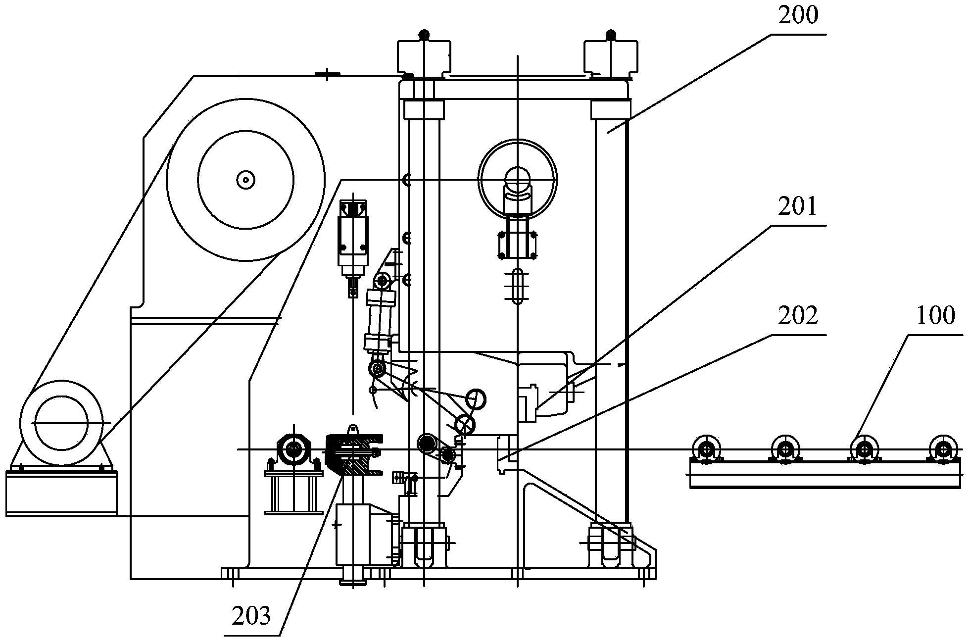
technical field [0001] The invention relates to the technical field of shearing systems, more specifically, to a shearing system to length and a shearing to length method. Background technique [0002] The current hot-rolled round steel is mainly φ12mm~φ65mm hot-rolled round steel, with an annual output of 300,000 tons. Such as figure 1 As shown, the product is mainly cut by a cut-to-length shearing system, which consists of a cold shear 200, a sizing machine, and a conveying roller table 100. The cold shear 200 is made up of a full head baffle 203, an upper shearing edge 201, a lower shearing edge 202, a crank mechanism, etc., and one of its functions is to cut off rolling defects at the head and tail of the double-foot material. [0003] Conveyor roller table 100 rotates forward to move the double-foot material along the direction of steel ( figure 1 The middle steel material advances in the direction from left to right) and enters the cold shear 200. The head of the st...

Claims


Application Information

Patent Timeline
IPC IPC(8): B23D15/00B23D33/04
Inventor 闻小德张军
Owner LAIWU IRON & STEEL GRP
Learn More