
An edge shielding device of the cooling system after medium and heavy plate rolling

A shielding device and cooling system technology, applied in metal rolling, metal rolling, workpiece surface treatment equipment, etc., can solve problems such as difficult maintenance, broken chains, and simple structure of chain edge shielding devices, and achieve simple device structure , Safe and reliable operation, and the effect of improving control accuracy

Active Publication Date: 2016-03-30
NORTHEASTERN UNIV LIAONING
View PDF5 Cites 0 Cited by
  • Summary
  • Abstract
  • Description
  • Claims
  • Application Information

AI Technical Summary

Problems solved by technology

The existing layer edge shielding device usually adopts chain transmission, but due to the simple structure of the chain edge shielding device, it is difficult to maintain, and mechanical failures such as chain breakage often occur during use, resulting in the failure of normal use of the equipment

Method used


Image

  • An edge shielding device of the cooling system after medium and heavy plate rolling
  • An edge shielding device of the cooling system after medium and heavy plate rolling
  • An edge shielding device of the cooling system after medium and heavy plate rolling

Examples


Embodiment Construction

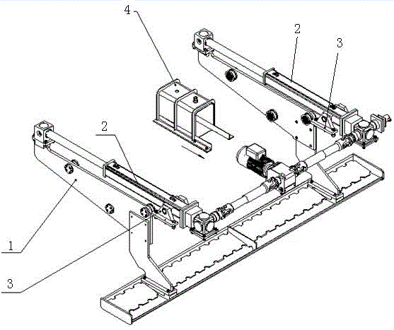
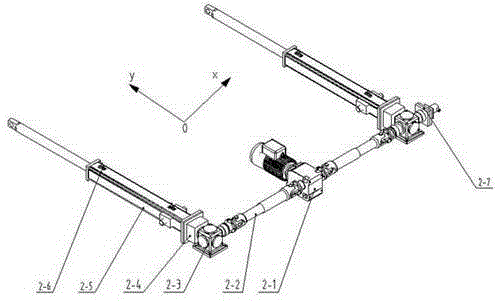
[0016] see figure 1 , the edge shielding device of the medium and heavy plate post-rolling cooling system of the present invention includes a unit shielding bracket assembly 1, an electric cylinder linkage assembly 2, a push rod support assembly 3 and a motor shield assembly 4; the unit shielding bracket assembly 1 is connected by bolts On the electric cylinder linkage assembly 2, it can be connected with the bolts to the cylinder body and the power group rod 2-5 of the electric cylinder linkage assembly 2 (see image 3 ) stretches and moves. The push rod end of the electric cylinder linkage assembly 2 is fixedly connected to the bracket assembly 1 , and the cylinder end of the electric cylinder linkage assembly 2 is connected to the push rod support assembly 3 .

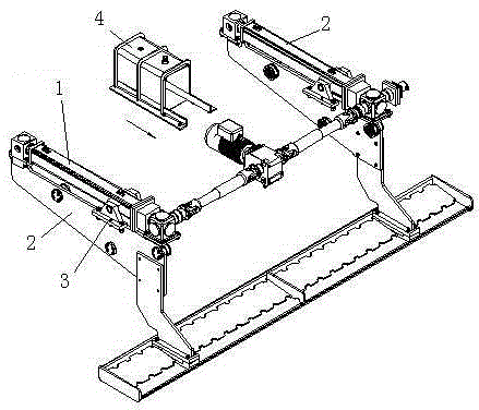
[0017] figure 1 , the push rod of the electric cylinder linkage assembly 2 is in the extended state, and figure 2 in the state of income.

[0018] image 3 It is a structural diagram of the electric cylinder l...


PUM


Abstract

The invention discloses an edge shielding device for a post-rolling cooling system for medium and thick plates. The edge shielding device includes a unit shielding bracket assembly (1), an electric cylinder linkage assembly (2), and a push rod support assembly (3). and motor shield assembly (4); the unit shielding bracket assembly (1) is connected to the electric cylinder linkage assembly (2) through bolts; the push rod end of the electric cylinder linkage assembly (2) is fixedly connected to the unit shield Bracket assembly (1), the cylinder end of the electric cylinder linkage assembly (2) is connected to the push rod support assembly (3). The invention effectively solves the problem of overcooling of the edge of the steel plate during the actual cooling of the steel plate by the ultra-fast cooling equipment, so that the steel plate can obtain ideal structure and performance. The use of advanced transmission equipment and control systems improves control accuracy. The contraction movement of the main transmission element adopts the screw principle, which effectively avoids the dangerous disadvantages of using hydraulic and cylinder contraction components in steel plants.

Description

technical field [0001] The invention belongs to the technical field of steel rolling automatic control, and in particular relates to an edge shielding device of a cooling system for a medium-thick plate after rolling. Background technique [0002] Controlled rolling and controlled cooling technology, namely TMCP (ThermoMechanicalControlProcess), is one of the greatest achievements of the steel industry in the 20th century. TMCP promotes the continuous renewal and development of the steel industry and supports the progress of human society. Controlled rolling has been implemented in the field of hot-rolled steel materials based on experience for a long time. Its core is to control the austenite temperature by controlling the heating temperature, rolling temperature, deformation system and other process parameters on the basis of adjusting the chemical composition of the steel. state and the microstructure of phase transition products, so as to achieve the purpose of controll...

Claims


Application Information

Patent Timeline
Patent Type & Authority Patents(China)
IPC IPC(8): B21B45/02B21B37/76
Inventor 王昭东田勇王丙兴韩毅张志福贾维维徐义波王国栋
Owner NORTHEASTERN UNIV LIAONING
Learn More