
Fuse assembly

一种熔断器、组件的技术,应用在电气元件、电路、紧急保护装置等方向,能够解决不利影响等问题

Active Publication Date: 2014-06-04
ANDEN CORP
View PDF5 Cites 0 Cited by
  • Summary
  • Abstract
  • Description
  • Claims
  • Application Information

AI Technical Summary

Problems solved by technology

When a contact fault occurs in a fuse subassembly, a voltage drop may occur at the terminal of the contact fault, and the operation of an electrical or electronic device connected to the fuse subassembly may be adversely affected due to such a voltage drop

Method used


Image

  • Fuse assembly
  • Fuse assembly
  • Fuse assembly

Examples


Embodiment Construction

[0030] Hereinafter, the present invention will be described by way of embodiments with reference to the accompanying drawings.

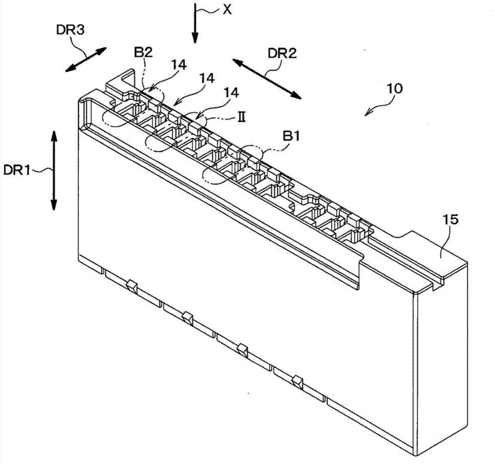
[0031] Such as Figure 1A As shown, the electrical connector box 10 has a plurality of fuse mounting portions 14, a fuse subassembly 12 (shown in Figure 6 and Figure 7A to Figure 7D ) mounted to each fuse mounting section 14. For example, the electrical connector box 10 is a fuse box for a vehicle, or a relay box having a plurality of fuse mounting parts 14 and electronic parts and / or components (for example, relays). For example, the electrical connector box 10 is installed in an engine room of a vehicle. The housing 15 forming a part of the housing of the electrical connector box 10 is made of resin such as PBT resin, PP resin, or the like.

[0032] The structure of the fuse mounting portion 14 of the electrical connector box 10 will be described. Although the electrical connector box 10 has a plurality of fuse mounting portions 14 arranged i...


PUM


Abstract

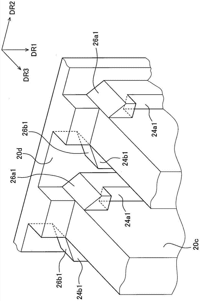
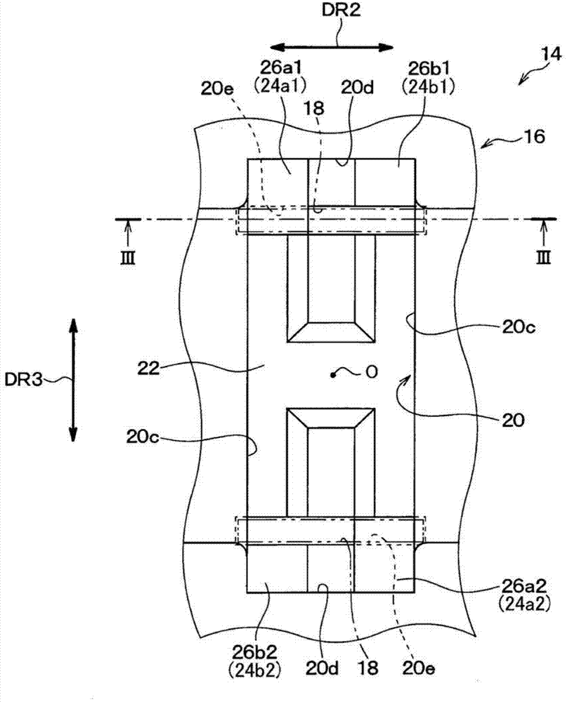
The invention provides a fuse assembly. A first and a second pairs of projecting portions (24a1, 24b1, 24a2, 24b2) are provided in a cavity portion (16) of a fuse mounting portion (14) made of resin. An upper end surface (26a1, 26b1, 26a2, 26b2) of each projecting portion (24a1, 24b1, 24a2, 24b2) is tapered, so as to guide a pair of male terminals (60) of a fuse sub-assembly (12) toward a corresponding female terminals (18) attached to the cavity portion (16), when the fuse sub-assembly (12) is inserted into the cavity portion (16). A gap (CLS) is formed between the fuse sub-assembly (12) and the tapered upper end surfaces in a fuse-mounted condition, in which the fuse sub-assembly (12) is in contact with a stopper portion (22) of the cavity portion (16), in order to prevent contact failure caused by thermal shock.

Description

technical field [0001] The present invention relates to a fuse assembly, and more particularly, to a structure of a fuse mounting portion of an electrical connector box to which a fuse subassembly is mounted. Background technique [0002] Fuse assemblies are known in the art, for example, as disclosed in Japanese Patent No. 4,238,783, which discloses the structure of a fuse mounting portion of an electrical connector box to which a fuse subassembly is mounted. install part. According to the structure of the fuse mounting part of the prior art described above, two types of fuse subassemblies can be mounted to the electrical connector box, wherein the outer dimension of the fuse subassembly in the direction of fuse insertion (more precisely, The length of the fuse subassemblies in the height direction) are different from each other. A pair of ribs are provided in the cavity in a width direction of the cavity of the housing for the electrical connector box, each of which prot...

Claims


Application Information

Patent Timeline
Patent Type & Authority Applications(China)
IPC IPC(8): H01H85/20
CPCH01H85/165H01H85/2035H01H85/0417H01H2085/207H01H2085/2075H01H2085/208H01H2085/2085H01H2085/209
Inventor 佐藤浩一铃木博久
Owner ANDEN CORP
Learn More