


Quick Research
Generate reliable direction feasibility study reports for your R&D in just a few steps.

Technical Q&A
Discover and master advanced knowledge NOW. Basics, ideas, possibilities, all at once.

Find Solutions
As an expert in R&D theories, this can generate solutions to your technical problems instantly.

Evaluate Feasibility
Analyze your overall solution with one click, know your potential R&D risks in advance.

Monitor Landscape
Get weekly tech updates, stay abreast of the latest tech innovations and key insights.
Liquid crystal display device
A technology of liquid crystal display device and liquid crystal panel, which is applied in the direction of nonlinear optics, instrumentation, optics, etc., and can solve problems such as the distance between the display area and the light-shielding film becomes closer, the influence of the display is large, and the display is blurred.
- Summary
- Abstract
- Description
- Claims
- Application Information
AI Technical Summary
Problems solved by technology
Method used
Image


Examples
Embodiment approach 1
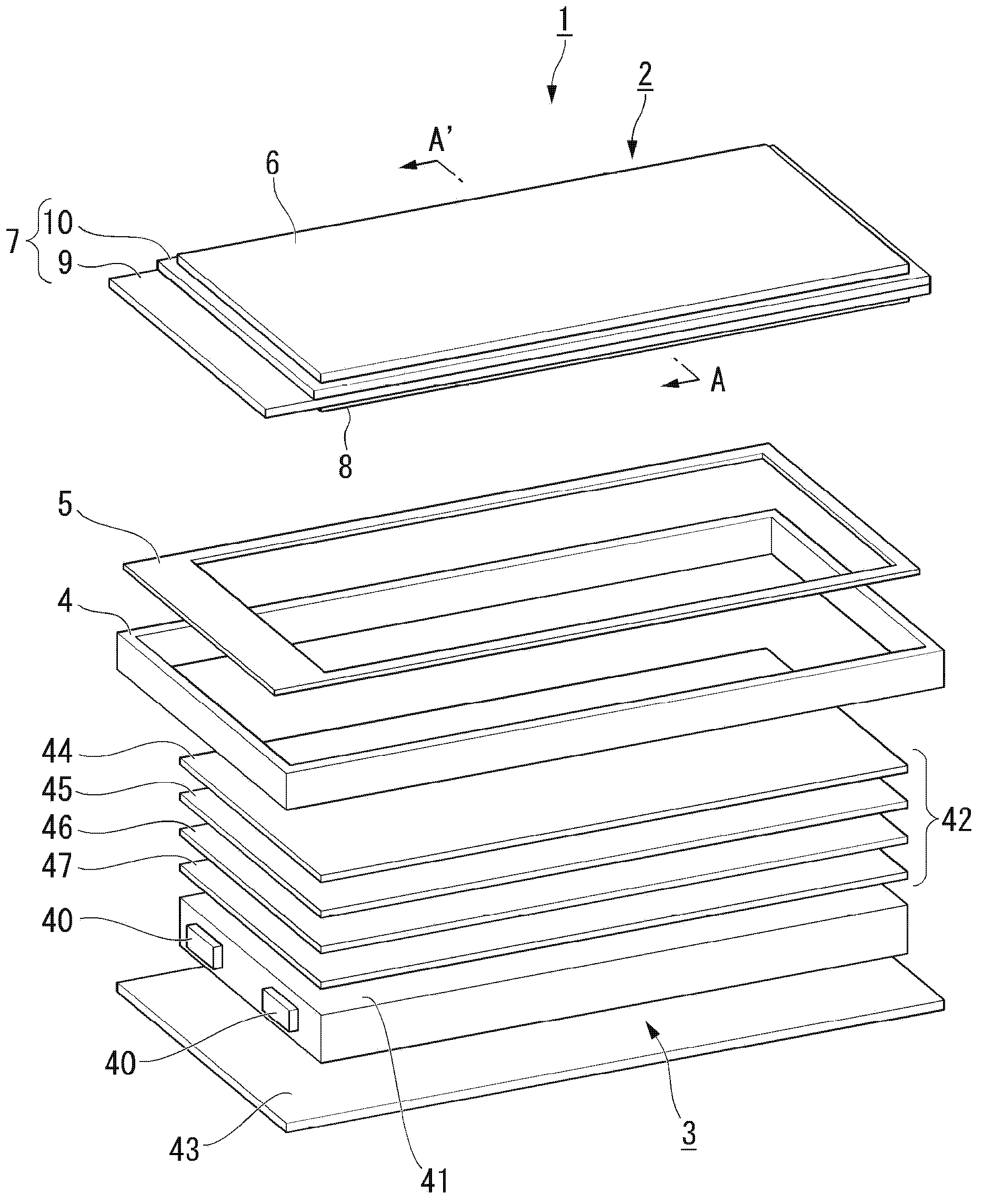
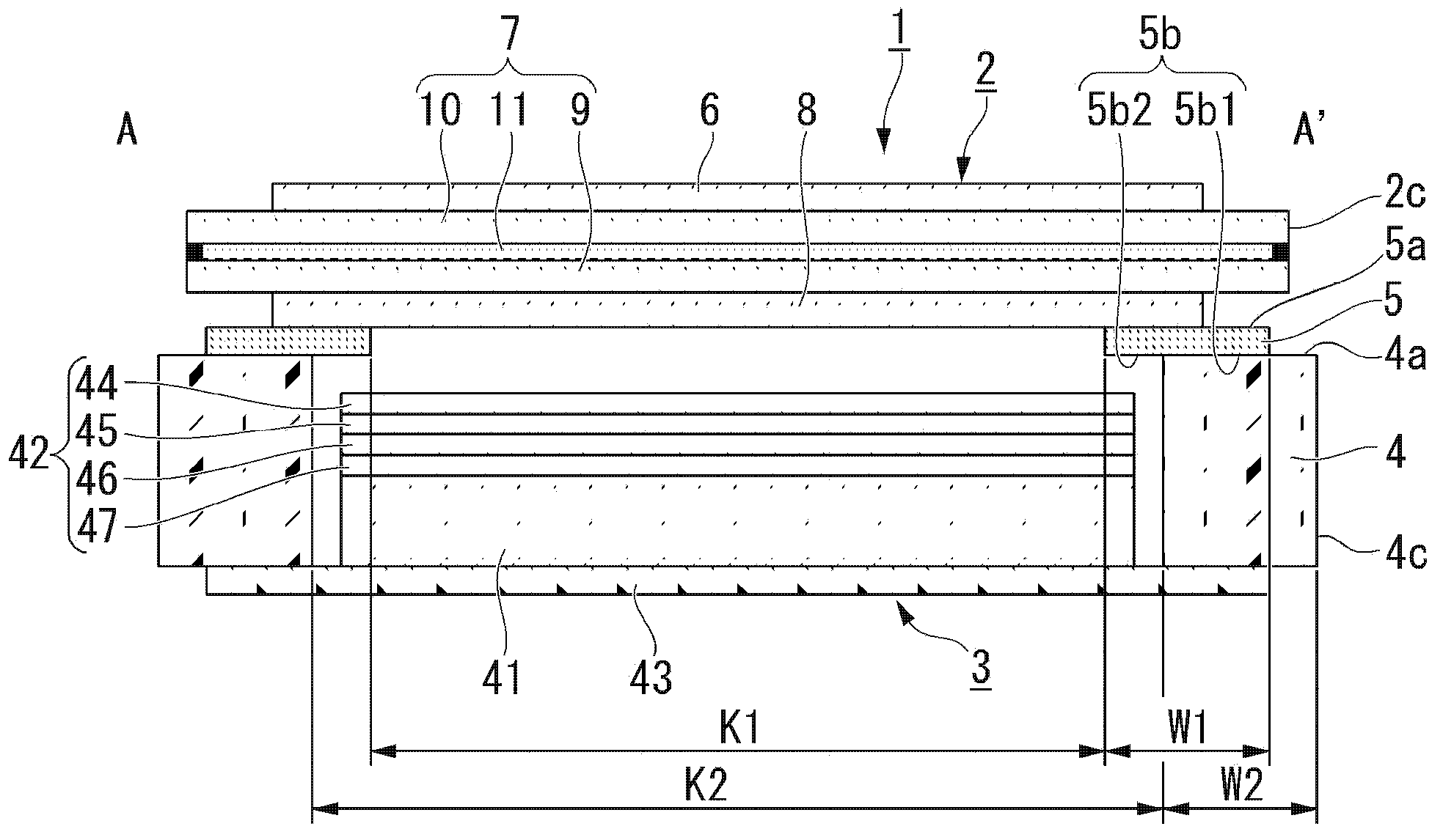
[0038] Use below Figure 1 to Figure 4 The liquid crystal display device of Embodiment 1 will be described.
[0039] In each of the following figures, in order to make each component easier to see, it may be shown with a different scale depending on the component.
[0040] The liquid crystal display device 1 of the present embodiment is, for example, figure 1 As shown, a liquid crystal panel 2 , a backlight 3 , a frame 4 , and a tape 5 for bonding are provided. The backlight 3 is configured in figure 1 The lower side of the middle liquid crystal panel 2. The backlight 3 emits light for illuminating the liquid crystal panel 2 . The backlight 3 of the present embodiment corresponds to the lighting device in the claims. The frame 4 supports the liquid crystal panel 2 and the backlight 3 . The joining tape 5 joins the liquid crystal panel 2 and the frame 4 .
[0041] In the liquid crystal display device 1 , light emitted from the backlight 3 is modulated for each pixel of t...
Embodiment approach 2
[0076] Use below Figure 5 Embodiment 2 will be described.
[0077] The basic structure of the liquid crystal display device of the present embodiment is the same as that of the first embodiment. The liquid crystal display device of this embodiment differs from Embodiment 1 only in the structure of the bonding tape. Therefore, in the present embodiment, the joining tape will be described.
[0078] exist Figure 5 , for the same as that of Embodiment 1 image 3 Common structural elements are given the same reference numerals.
[0079] Such as Figure 5 As shown, in the joining tape 54 of this embodiment, the colorless and transparent adhesive layer 51 is provided on the first surface 49 a of the base material 49 . The color of the first surface 54 a of the joining tape 54 reflects the color of the base material 49 . The color of the first surface 54 a of the joining tape 54 is black in which the lightness of an achromatic color is 1 or more and 5 or less in the Munsell c...
Embodiment approach 3
[0085] Use below Figure 6 Embodiment 3 will be described.
[0086] The basic structure of the liquid crystal display device of the present embodiment is the same as that of the first embodiment. The liquid crystal display device of this embodiment differs from Embodiment 1 only in the structure of the bonding tape. Therefore, in the present embodiment, the joining tape will be described.
[0087] exist Figure 6 , for the same as that of Embodiment 1 image 3 Common structural elements are given the same reference numerals.
[0088] Such as Figure 6 As shown, in the joining tape 57 of this embodiment, the colorless and transparent adhesive layer 51 is provided on the first surface 49 a of the base material 49 . The color of the first surface 57 a of the joining tape 57 reflects the color of the base material 49 . The color of the first surface 57 a of the joining tape 57 is black in which the lightness of an achromatic color is 1 or more and 5 or less in the Munsell c...
PUM
| Property | Measurement | Unit |
|---|---|---|
| reflectance | aaaaa | aaaaa |
| reflectance | aaaaa | aaaaa |
| reflectance | aaaaa | aaaaa |
Abstract
Description
Claims
Application Information
 - R&D Engineer
- R&D Manager
- IP Professional
- Industry Leading Data Capabilities
- Powerful AI technology
- Patent DNA Extraction
Browse by: Latest US Patents, China's latest patents, Technical Efficacy Thesaurus, Application Domain, Technology Topic, Popular Technical Reports.
© 2024 PatSnap. All rights reserved.Legal|Privacy policy|Modern Slavery Act Transparency Statement|Sitemap|About US| Contact US: help@patsnap.com