
Hinged rectangular-pipe assembled buckling restrained brace with end rotation limiting function

A kind of anti-buckling bracing and prefabricated technology, applied in the direction of anti-vibration, building components, etc., can solve the problems of high production precision, increased production cost, poor durability, etc., and achieve the effect of convenient precision control, easy production thickness, and easy processing accuracy.

Inactive Publication Date: 2014-06-04
TSINGHUA UNIV
View PDF4 Cites 14 Cited by
  • Summary
  • Abstract
  • Description
  • Claims
  • Application Information

AI Technical Summary

Problems solved by technology

[0004] The commonly used reinforced concrete peripheral constrained section and steel and concrete combined peripheral constrained section mainly have the following disadvantages: (1) The manufacturing precision of this type of component is high, resulting in increased manufacturing costs, especially when pouring concrete, no matter what kind of delicate Formwork materials and support methods are difficult to guarantee the reserved precision requirements between the inner core and the periphery; (2) Wet operations such as pouring concrete have affected the production and construction, and its precision control is difficult; (3) The coating is in The isolation material on the surface of the core component is mostly epoxy resin, which has a single variety, and its durability is poor, and it is easy to detach from the surface of the core

Method used


Image

  • Hinged rectangular-pipe assembled buckling restrained brace with end rotation limiting function
  • Hinged rectangular-pipe assembled buckling restrained brace with end rotation limiting function
  • Hinged rectangular-pipe assembled buckling restrained brace with end rotation limiting function

Examples


Embodiment Construction

[0024] In the present invention, upper and lower wings are added to the end of the in-line inner core member to form a reinforced section of the inner core member; the reinforced section of the inner core member is divided into two types: the extended section and the restraint section, and the length of the reinforced restraint section of the inner core member should ensure that the support is under the action of the axial tension load. There is still a certain length below.

[0025] At the same time, in order to meet the requirement of free expansion and contraction of the reinforcement section of the inner core member in the longitudinal direction, the end of the flat steel plate constraining the square steel pipe is grooved, and the groove is locally reinforced, and the length of the reinforcement is consistent with the length of the groove; the end of the outer restraint member The local reinforcement at the center is mainly realized by setting the outer cover plate of chan...


PUM


Abstract

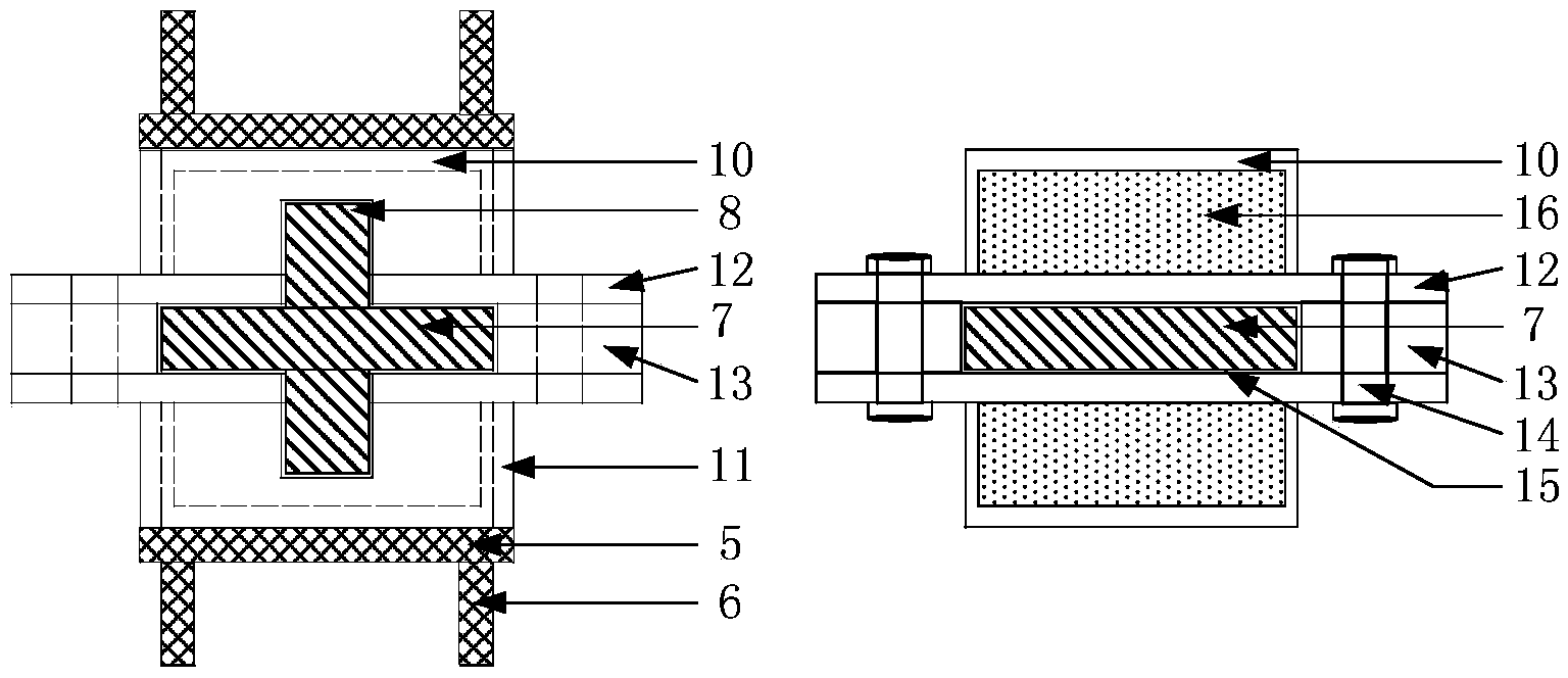
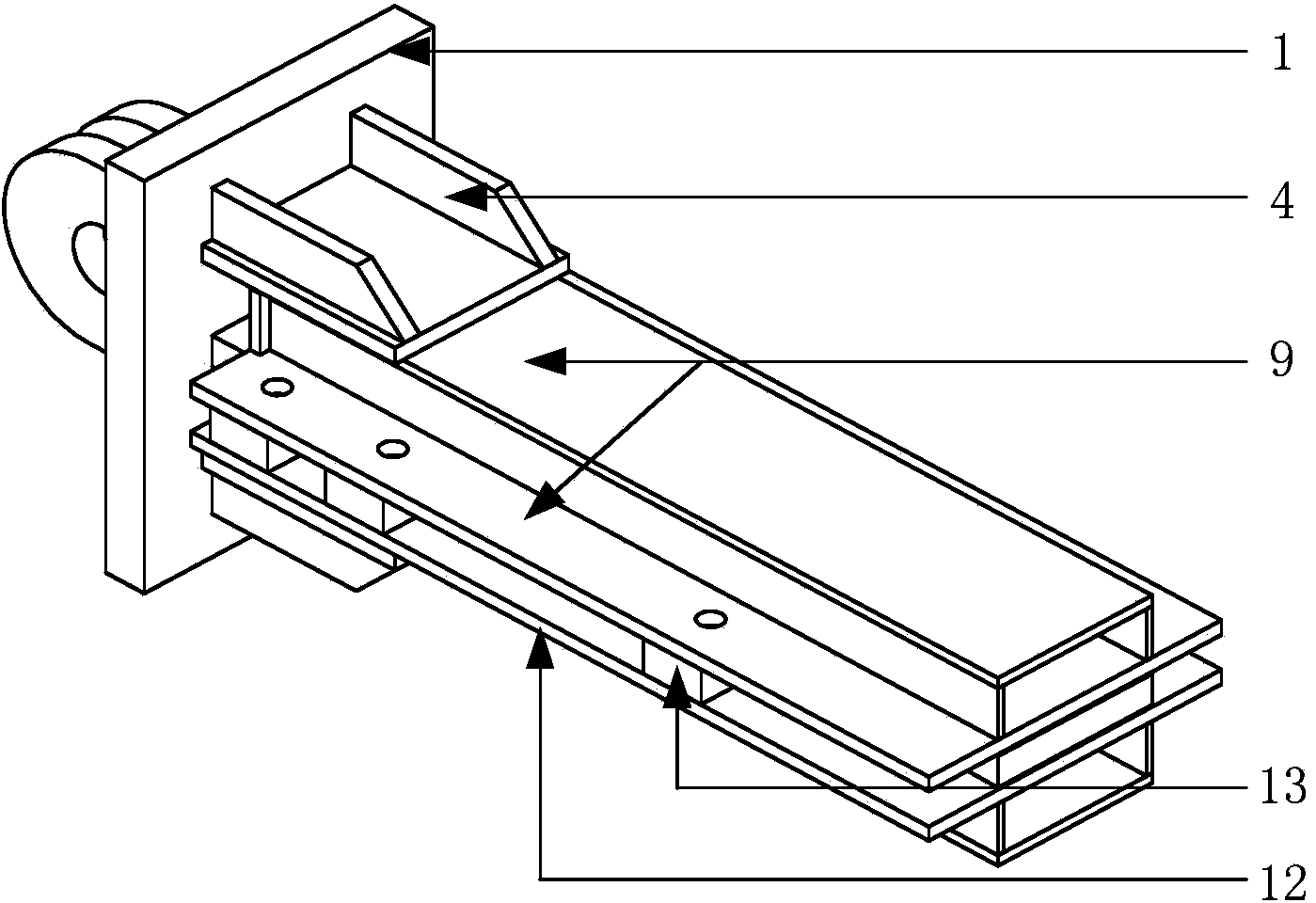
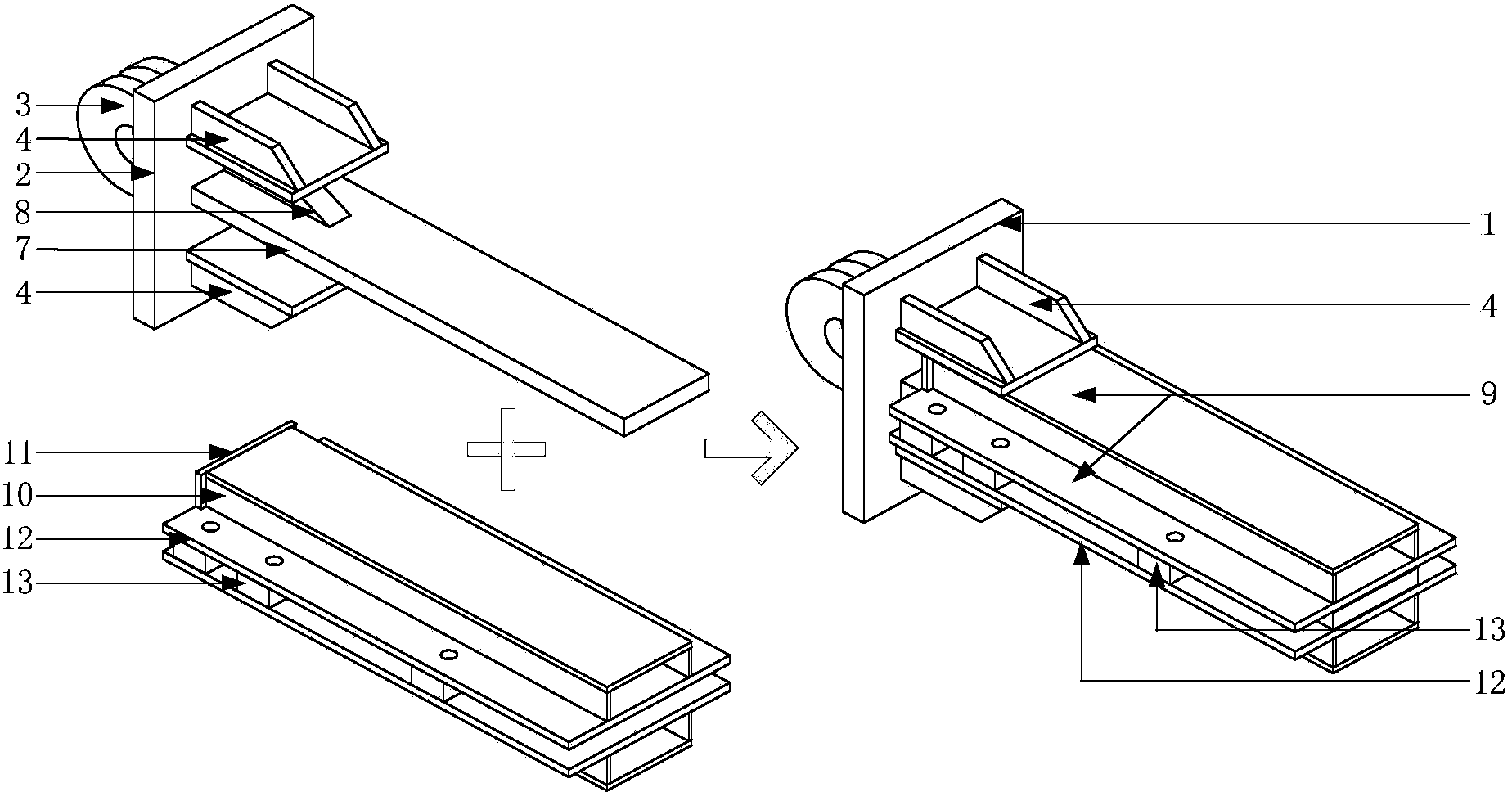
The invention relates to a hinged rectangular-pipe assembled buckling restrained brace with an end rotation limiting function and belongs to the field of structural engineering. The rectangular-pipe assembled buckling restrained brace comprises an I-shaped core member, restrained rectangular steel pipes, vulcanite, steel base plates and high-strength bolts. The core member is a flat steel plate with low strength and high ductility, the vulcanite is adhered on the surface of an area wrapped by a restraining member, the high-strength bolts penetrates bolt holes on the restraining member and the steel base plates, and the two restrained rectangular steel pipes are integrated to form a peripheral restraining member by applying pretension force of the bolts. Four reinforcing benches are respectively welded on end plates. Each reinforcing bench is composed of a bench cover plate and two bench rib plates, wherein the bench cover plate tightly clings to the peripheral restraining member of the buckling restrained brace and reserves a gap with the same. Two hinge joints are provided and are welded by the end plates and lug plates. The peripheral restraining member can effectively limit end rotation angles of hinged rectangular-pipe assembled buckling restrained brace, so that the peripheral restraining member generates a reverse bending moment action.

Description

technical field [0001] The patent relates to a hinged rectangular tube assembly type anti-buckling support that restricts end rotation, and belongs to the technical field of structural engineering. Background technique [0002] Buckling-resistant bracing members are generally composed of two parts: the inner core member and the outer restraint member. After the Northridge earthquake in the United States in 1994 and the Kobe earthquake in Japan in 1995, engineers began to realize that buckling-resistant bracing members had an excellent effect on energy dissipation and shock absorption, and a large number of engineering practices began in Japan and the United States. Because buckling-resistant bracing members have the dual functions of "energy dissipation" and "supporting", in areas with high seismic fortification intensity, buckling-resistant bracing members are considered to be one of the best energy-dissipating and shock-absorbing members. my country's high-rise buildings h...

Claims


Application Information

Patent Timeline
IPC IPC(8): E04B1/98
Inventor 姜子钦郭彦林袁星张旭乔
Owner TSINGHUA UNIV
Learn More