
Seat device

A technology for seats and seat cushions, applied in vehicle seats, transportation and packaging, special positions of vehicles, etc., can solve problems such as disadvantages

Inactive Publication Date: 2014-06-04
FAURECIA AUTOSITZE
View PDF6 Cites 1 Cited by
  • Summary
  • Abstract
  • Description
  • Claims
  • Application Information

AI Technical Summary

Problems solved by technology

[0003] Precisely in the case of thicker seat cushions, this construction is disadvantageous, since the forces to be exerted on the occupant cannot be optimally utilized with thicker seat cushions and the resulting longer bellows body stroke lengths. pass to passengers

Method used


Image

  • Seat device
  • Seat device
  • Seat device

Examples


Embodiment Construction

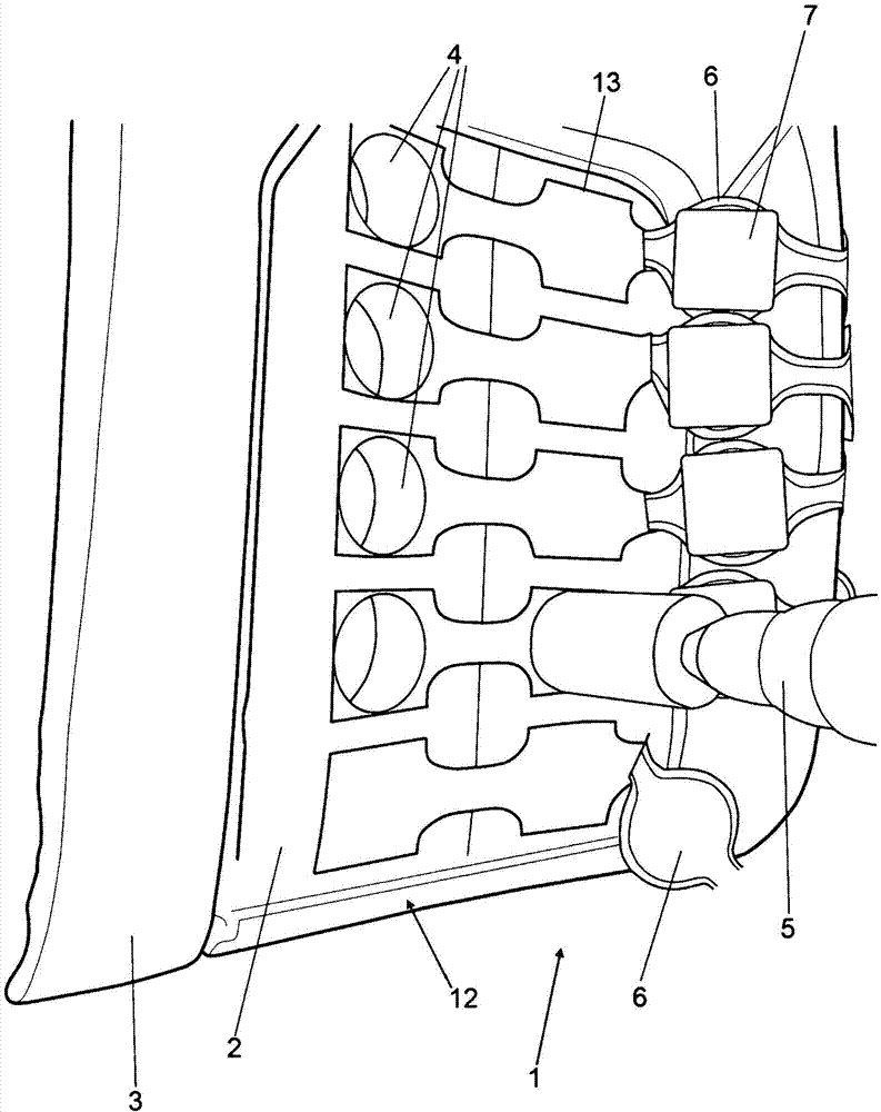
[0015] figure 1 The seat device shown (in the following in particular the vehicle seat) is the seat back. The backrest has a seat cushion area 2 to which side bolsters 3 are attached on both sides. The seat cushion area 2 is hereinafter referred to simply as a cushion. Pad 2 ( figure 1 The front side 12 ) of which is shown has a plurality of recesses 4 , the recesses being produced in the mat material by means of a tool 5 . The recesses 4 are preferably formed as through holes through the entire material of the pad 2 . A recess 13 for an additional support plate 7 may also be provided in the front side 12 between the recess 4 and the front side 12 .

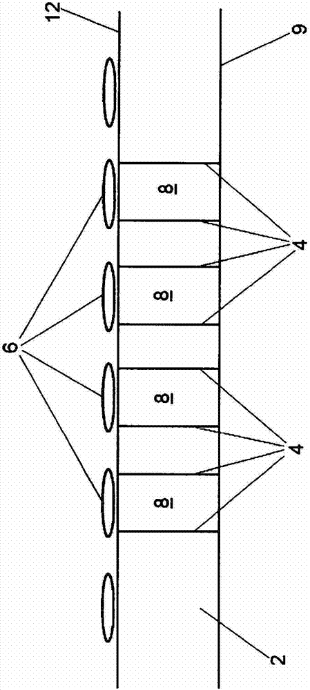
[0016] figure 2 The shown sectional view shows a section of the pad 2 with the through-opening 4 extending between the front side 12 and the back side 9 of the pad 2 . Support bodies 8 are inserted into these through holes 4 preferably in a form-fitting manner. The massaging element 6 rests on the support body 8 at the ...


PUM


Abstract

The invention relates to a seat device and especially relates to an automobile seat device. The device includes a seat pad zone (2) made of a first material and especially the first pad material and at least massage element (6) installed in the seat pad zone (2). The seat pad zone includes a pad front face (12) facing a user and a pad back face (9) back to the user. According to the invention, in order to support the massage element from the back, a support body (8) made of the second material and especially the second pad material is arranged in the seat pad zone. The second material has greater rigidness than the first material.

Description

technical field [0001] The present invention relates to a seat device. Background technique [0002] A motor vehicle seat with a massage device is known, for example, from US Pat. No. 7,727,171 B2. The massage device has a plurality of massage elements which are distributed over the seat surface. These known massaging elements are designed in the form of bellows and can be acted upon pneumatically. For this purpose, the bellows body made of a plastic bladder is inserted into the seat cushion and its height can be varied by inflation and deflation in order to vary the compression force on the vehicle occupants. The massaging elements guided by the seat pad are supported on the back of the pad on the support plate in order to be able to exert a corresponding counterforce. [0003] Precisely in the case of thicker seat cushions, this construction is disadvantageous because the forces to be exerted on the occupant cannot be optimized optimally with thicker seat cushions and t...

Claims


Application Information

Patent Timeline
Patent Type & Authority Applications(China)
IPC IPC(8): B60N2/44B60N2/90
CPCB60N2/7017B60N2/448B60N2/976
Inventor C·J·斯利瓦
Owner FAURECIA AUTOSITZE
Learn More