Near Infrared Cut Filter
A cut-off filter, near-infrared technology, applied in the direction of instruments, optics, optical components, etc., can solve the problems of small refractive index difference, insufficient reduction of stop band transmittance, inability to fully form stop band, etc., to achieve incident angle dependence inhibitory effect
- Summary
- Abstract
- Description
- Claims
- Application Information
AI Technical Summary
Problems solved by technology
Method used
Image
Examples
Embodiment
[0168] Hereinafter, it demonstrates more concretely with reference to an Example.
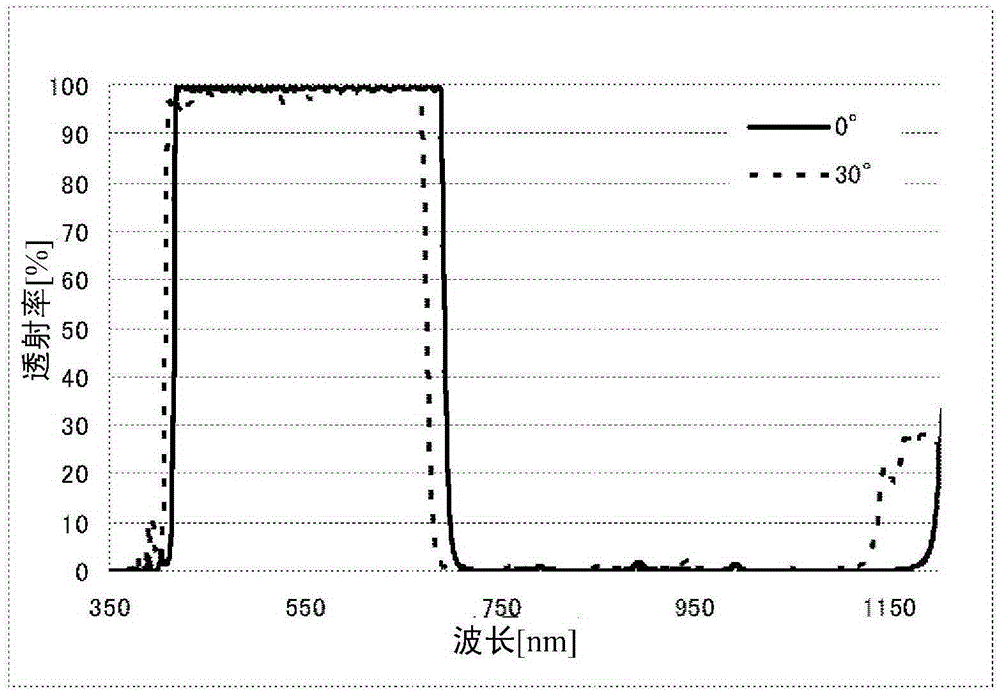
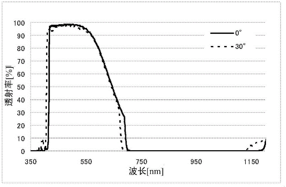
[0169] Examples 1 to 4 are examples of the near-infrared cut filter of the present invention. In addition, Examples 5 to 14 are examples in which the spectral transmittance at each incident angle was calculated by optical simulation for the laminated film of each structure.
example 1
[0171] The near-infrared cut filter has a structure in which one main surface of the transparent substrate has a transmission band forming portion which is a part of the optical multilayer film, and has a stop band forming portion which is a part of the optical multilayer film on the other main surface. Here, the transparent substrate is colorless transparent glass (manufactured by SCHOTT, trade name: D263, thickness: 0.3 mm), or near-infrared cut glass (manufactured by Asahi Glass Co., Ltd., trade name: NF- 50T, thickness: 0.26mm).
[0172] The transmissive zone constituting part used the transmissive zone constituting part having the structure shown in Table 1 in the first form. The number of layers in the table is the number of layers from the transparent substrate side. Here, in the TiO that will be used as a high refractive index film 2 The film is denoted as H, and Ta as the middle refractive index film 2 o 5 The film is denoted as M, and SiO as a low refractive inde...
example 2
[0189] The near-infrared cut filter has a configuration in which a transmission band constituting part of the optical multilayer film is formed on one main surface of a transparent substrate, and a stop band constituting part of the optical multilayer film is formed on the other main surface. Here, the transparent substrate and the barrier band constituting portion are the same as in Example 1.
[0190] The transmissive zone constituting part used the transmissive zone constituting part of the second embodiment having the structure shown in Table 6. FIG. Here, in the TiO that will be used as a high refractive index film 2 The film is denoted as H, and Ta as the middle refractive index film 2 o 5 When the film is denoted as M, the transmission band constituting part is basically constituted by the basic unit of [HM]. In addition, the number of layers is 52 layers, TiO 2 The average optical film thickness T of the film H 210.7nm, Ta 2 o 5 The average optical film thicknes...
PUM
| Property | Measurement | Unit |
|---|---|---|
| refractive index | aaaaa | aaaaa |
| refractive index | aaaaa | aaaaa |
| transmittivity | aaaaa | aaaaa |
Abstract
Description
Claims
Application Information
 - R&D Engineer
- R&D Manager
- IP Professional
- Industry Leading Data Capabilities
- Powerful AI technology
- Patent DNA Extraction
Browse by: Latest US Patents, China's latest patents, Technical Efficacy Thesaurus, Application Domain, Technology Topic, Popular Technical Reports.
© 2024 PatSnap. All rights reserved.Legal|Privacy policy|Modern Slavery Act Transparency Statement|Sitemap|About US| Contact US: help@patsnap.com


