An ion transport device

A technology of ion transport and suit, applied in the direction of accelerators, electrical components, etc., can solve the problem that ion transport can not meet the application requirements, and achieve the effect of flexible and efficient control and narrowing of the distance.

Inactive Publication Date: 2016-10-26
PEKING UNIV
View PDF5 Cites 0 Cited by
  • Summary
  • Abstract
  • Description
  • Claims
  • Application Information

AI Technical Summary

Problems solved by technology

[0003] In view of this, the object of the present invention is to provide an ion transport device to solve the problem that the ion transport in the prior art cannot meet the application requirements

Method used


Image

  • An ion transport device
  • An ion transport device
  • An ion transport device

Examples


Embodiment Construction

[0025] Various embodiments of the invention will be described in more detail below with reference to the accompanying drawings. In the various drawings, the same elements are denoted by the same or similar reference numerals. For the sake of clarity, various parts in the drawings have not been drawn to scale.

[0026] "Front side", "rear side", "front end" and "rear end" in the present invention are defined according to the ion beam transmission direction, the side close to the laser target is defined as the front side and the front end, and the side away from the laser target Defined as rear side, rear end.

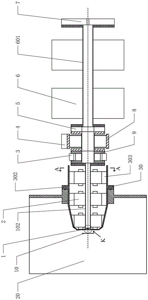
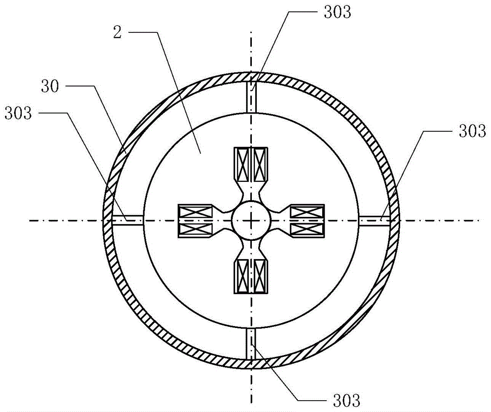
[0027] Such as figure 1 As shown, the ion transport device of the present invention mainly includes: a connecting sleeve 30 , a collecting slit plate 1 , a collecting lens group 2 , a correction magnet 3 , a molecular pump 4 and an auxiliary collecting lens group 6 .

[0028] Such as figure 1 As shown, the front end of the ion transport device of the present inventio...


PUM


Abstract

The invention relates to an ion transportation device. The ion transportation device is characterized by comprising a connecting sleeve, a collection slit plate, a collection lens group, a correction magnet, a molecular pump and an auxiliary collection lens group, wherein collection slits are arranged on the collection slit plate, the collection lens group, the correction magnet, the molecular pump and the auxiliary collection lens group are sequentially arranged on the rear side of the collection slit plate according to the transmission direction of ion beams, and the connecting sleeve is nested on the collection slit plate and the collection lens group. The ion transportation device provided by the invention is used for collection and transportation of ions in an ion laser accelerator; one part of the ion transportation device can be inserted into the inside of a laser target chamber due to the arrangement of the connecting sleeve, so that the distance between the ion transportation device and a laser target can be further reduced, the control of ion beams by the ion transportation device is flexible and high-efficient, and therefore the ion transportation device can meet different application requirements.

Description

technical field [0001] The invention relates to an ion transport device, in particular to an ion transport device in a laser accelerator. Background technique [0002] Many research institutes in the world are conducting research on the application of laser accelerators, but the research is still in the exploratory stage. This is because the ion beam produced by the laser accelerator has the characteristics of short pulse, high current intensity, and large energy dissipation, which has caused great troubles to the application of the ion beam. The pulse width of the ion beam generated by the laser accelerator is only tens of picoseconds, and each pulse contains 10 8 -10 11 ions, so the pulse current intensity can reach the ampere level. Moreover, the size of the initial beam spot of the ion beam is equal to that of the laser focal spot, which is only a few microns, resulting in a very strong space charge effect, a large envelope of the ion beam during transmission, and low...

Claims


Application Information

Patent Timeline
Patent Type & Authority Patents(China)
IPC IPC(8): H05H15/00
Inventor 尚勇朱昆颜学庆
Owner PEKING UNIV
Why Eureka
Try Eureka