Laser output device and control method thereof

A laser output device and control method technology, applied in the laser field, can solve the problems of lack of time monitoring function, unable to monitor laser output time, unable to monitor laser use time, etc., to achieve good market application value, effective management and maintenance effects

Active Publication Date: 2014-05-28
SHENZHEN JPT OPTO ELECTRONICS CO LTD
View PDF5 Cites 10 Cited by
  • Summary
  • Abstract
  • Description
  • Claims
  • Application Information

AI Technical Summary

Problems solved by technology

[0009] However, existing laser output devices, such as fiber lasers, laser marking machines, laser engraving machines, etc., lack time monitoring functions, for example, they cannot monitor the time of laser output, nor can they monitor the use time of lasers

Method used


Image

  • Laser output device and control method thereof
  • Laser output device and control method thereof
  • Laser output device and control method thereof

Examples


Embodiment Construction

[0035] In order to facilitate the understanding of the present invention, the present invention will be described in more detail below in conjunction with the accompanying drawings and specific embodiments. Preferred embodiments of the invention are shown in the accompanying drawings. However, the present invention can be implemented in many different forms and is not limited to the embodiments described in this specification. On the contrary, these embodiments are provided to make the understanding of the disclosure of the present invention more thorough and comprehensive.

[0036] It should be noted that when an element is referred to as being “fixed” to another element, it can be directly on the other element or there can also be an intervening element. When an element is referred to as being "connected to" another element, it can be directly connected to the other element or intervening elements may also be present. The terms "vertical", "horizontal", "left", "right" and...


PUM


Abstract

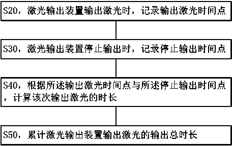
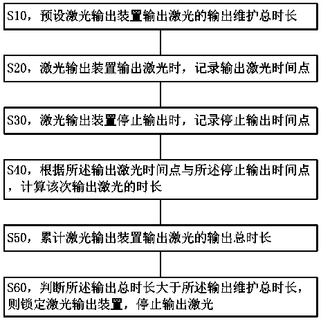
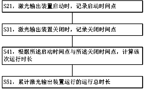
The invention discloses a laser output device and a control method thereof. The control method comprises the following steps: S02, recording the duration of the laser output device for outputting laser for each time; S50, accumulating the total duration of the laser output device for outputting laser. Through the technical scheme, the laser output can be monitored, so that the laser output device can be more effectively managed and maintained; the laser output device and the control method thereof are good in market application values.

Description

technical field [0001] The present invention relates to laser technology, in particular to a laser output device and a control method thereof. Background technique [0002] Laser output devices include lasers, laser equipment, instruments capable of outputting lasers, systems capable of outputting lasers, etc. For example, laser equipment includes YAG (yttrium aluminum garnet) laser marking machines, semiconductor laser marking machines, CO2 laser marking machines , Fiber laser marking machine, laser engraving machine, laser welding machine, laser cutting machine, laser scribing machine, etc. [0003] Specifically, a laser is a device capable of emitting laser light, which includes a device that uses the principle of stimulated radiation to amplify or oscillate light in certain excited substances. In 1954, the first microwave quantum amplifier was made, and a highly coherent microwave beam was obtained; in 1958, A.L. Xiao Luo and C.H. Towns extended the principle of microwa...

Claims


Application Information

Patent Timeline
IPC IPC(8): H01S3/10H01S3/131
Inventor 刘健成学平刘猛
Owner SHENZHEN JPT OPTO ELECTRONICS CO LTD
Why Eureka
Try Eureka