Dental implant

a technology for dental implants and implants, applied in dental implants, dental surgery, medical science, etc., can solve the problems of reducing affecting the masticatory function of the implant, and affecting the masticatory function, so as to reduce the occurrence of bad smell, and facilitate the separation of the crown

Active Publication Date: 2020-10-29
LEE JAE JOON
View PDF0 Cites 1 Cited by
  • Summary
  • Abstract
  • Description
  • Claims
  • Application Information

AI Technical Summary

Benefits of technology

[0008]According to the present invention, a dental implant has advantages of facilitating a simple separation of a crown through a cover screw coupled to an abutment and minimizing occurrence of bad smell, etc., thereby enabling a more efficient management and maintenance of the implant.
[0009]In addition, the dental implant may maintain a binding force between the fixture and the abutment through an anti-release member, thus having an advantage of solving problems such as breakage, loss of masticatory function, etc., due to the weakened binding force.

Problems solved by technology

However, when the dental implant requires management such as replacement of the crown, etc., it is difficult to separate and remove the crown, thus causing inconvenience to operators and patients.
Further, as cotton, etc., is filled into an inner passage of the abutment, which is used for fastening the abutment to the fixture, smell such as odor, etc., occurs as time passes after a procedure, thus causing a problem of giving discomfort to patients.
In addition, a lateral force is applied in a process of chewing food, so that a screw-coupling force of the abutment screw-coupled to the fixture becomes loose, thus having a problem of causing complications such as screw breakage, loss of masticatory function, etc.

Method used


Image

  • Dental implant
  • Dental implant
  • Dental implant

Examples


Embodiment Construction

[0015]Hereinafter, preferred embodiments of a dental implant according to the present invention will be described in detail with reference to the accompanying drawings. These embodiments are provided to more fully explain the present invention to those of ordinary skill in the art, and it should be noted that a shape and size of elements, an interval between the elements and the like in the accompanying drawings may be reduced or exaggerated to emphasize a clearer description.

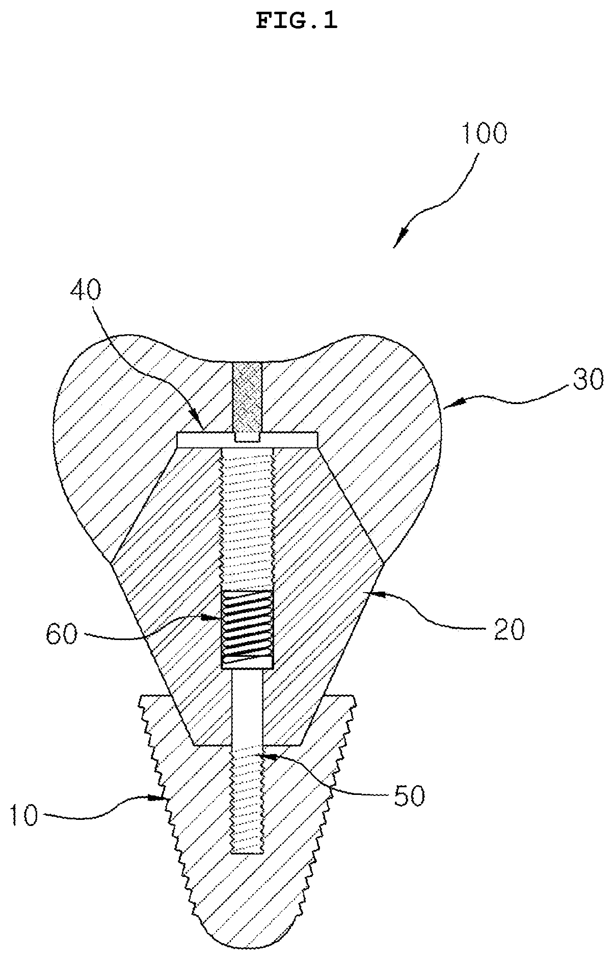
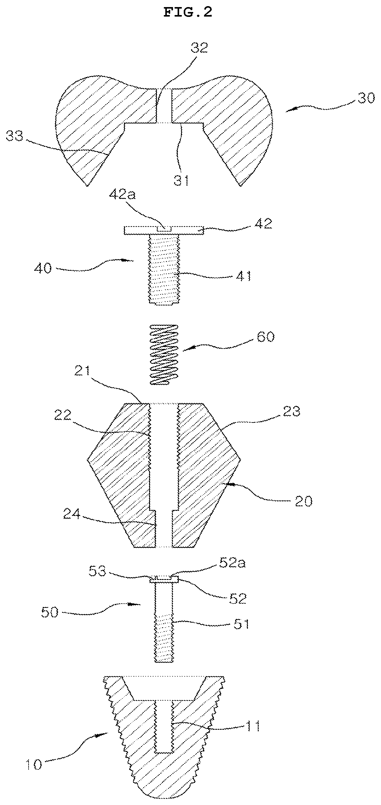
[0016]FIGS. 1 to 6 show examples of a configuration and operation of a dental implant according to one embodiment of the present invention. Thus, referring to the drawings, the dental implant (hereinafter referred to as “implant 100”) may first include a fixture 10, an abutment 20 and a crown 30 as a basic configuration.

[0017]The fixture 10 may be implanted into an alveolar bone to serve as a dental root for fixing the implant 100 as a whole.

[0018]The fixture 10 may have a screw thread formed on an outer circum...


PUM


Abstract

A dental implant includes a fixture implanted into an alveolar bone, an abutment fixed to an upper part of the fixture and having a core hole formed in a center of an upper surface of the abutment, a crown bonded to an upper outer side of the abutment and having a passage vertically formed through a center of the crown, and a cover screw having a screw screw-fastened to the core hole and a head in close contact between an upper surface of the abutment and a lower surface of the crow to cover the core hole, in which, when the screw is released by a tool passing through the passage, the head moves up so that the cover screw provides a separating force to the crown. The dental implant may facilitate a separation of the crown and prevent binding force from weakening, thereby enabling an efficient procedure and management.

Description

TECHNICAL FIELD[0001]The present invention relates to a dental implant, and more particularly to a dental implant for facilitating a separation of a crown and preventing a binding force from weakening.BACKGROUND ART[0002]An implant means a substitute that restores a lost human tissue. In particular, a dental implant means a substitute capable of functioning as a tooth, in such a way that a fixture, which is an artificial dental root, is implanted into and adheres to an alveolar bone, from which a natural dental root is taken out, in order to replace a dental root of a lost tooth, and a crown, which is an artificial tooth, is fixed to the fixture.[0003]The dental implant conventionally includes a fixture which is osseointegrated into an alveolar bone to perform a dental root function, an abutment fixed to the fixture, and a crown fixed to the abutment to carry out a tooth function.[0004]However, with regard to the conventional dental implant, the crown is fixedly bonded to the abutme...

Claims


Application Information

Patent Timeline
Patent Type & Authority Applications(United States)
IPC IPC(8): A61C8/00
CPCA61C8/0028A61C8/0042A61C8/0057A61C8/0068A61C8/0069A61C8/0078A61C8/0089A61C8/0022
Inventor LEE, JAE-JOON
Owner LEE JAE JOON
Why Eureka
Try Eureka