Pipeline test method and system

A test method and pipeline technology, applied in the field of measurement, can solve problems such as inaccurate pipeline measurement results and inability to perform pipeline measurement, so as to solve inaccurate measurement results, solve broken wires or short circuit faults, and achieve accurate measurement results Effect

Inactive Publication Date: 2014-05-28
GREE ELECTRIC APPLIANCES INC
View PDF4 Cites 5 Cited by
  • Summary
  • Abstract
  • Description
  • Claims
  • Application Information

AI Technical Summary

Problems solved by technology

[0005] In view of this, the present invention provides a pipeline testing method and system to solve the inaccurate pipeline measurement results and the phenomenon that pipeline measurement cannot be performed in the prior art

Method used


Image

  • Pipeline test method and system
  • Pipeline test method and system
  • Pipeline test method and system

Examples


Embodiment Construction

[0036] The following will clearly and completely describe the technical solutions in the embodiments of the present invention with reference to the accompanying drawings in the embodiments of the present invention. Obviously, the described embodiments are only some, not all, embodiments of the present invention. Based on the embodiments of the present invention, all other embodiments obtained by persons of ordinary skill in the art without making creative efforts belong to the protection scope of the present invention.

[0037] The embodiment of the present invention discloses a pipeline testing method and system to solve the inaccurate pipeline measurement results and the phenomenon that the pipeline measurement cannot be performed in the prior art.

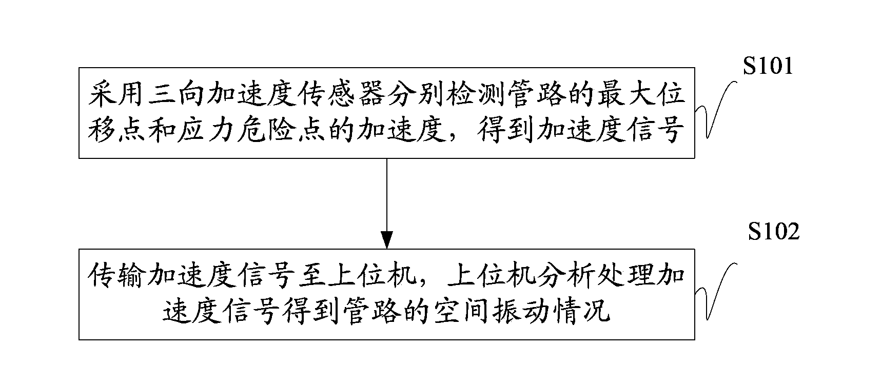
[0038] Specifically, the pipeline testing method disclosed in the embodiment of the present invention, such as figure 1 shown, including steps:

[0039] S101. Using a three-way acceleration sensor to respectively detect the acc...


PUM


Abstract

The invention discloses a pipeline test method and system. At first, analysis is performed according to the finite element analysis method to obtain the maximum displacement point and the stress dangerous point of the pipeline, and then, accelerated speeds at the maximum displacement point and the stress dangerous point of the pipeline are detected separately with a three-directional acceleration sensor, measurement is effectively performed for the maximum displacement point and the stress dangerous point of the pipeline, the measurement result is accurate; and the three-directional acceleration sensor has the anti-interference and shielding performances, so the problem of inaccurate measurement result caused by external interferences can be solved; and the three-directional acceleration sensor can be arranged on a small-diameter pipeline, so the measurement of the small-diameter pipeline can be realized; the broken or short-circuit failure is not easy to occur, so the problem that the measurement cannot be performed due to the broken or short-circuit failure in the prior art can be solved.

Description

technical field [0001] The present invention relates to the technical field of measurement, and more specifically, relates to a pipeline testing method and system. Background technique [0002] In the prior art, strain gauges are used to collect strain data for pipeline testing. Specifically, the strain gauges are pasted on the stress risk points of the test pipeline, and the strain gauges and strain gauges are connected by extension lines, and then the strain gauges Connect to the tester via Ethernet. [0003] With the vibration and deformation of the test pipeline, the strain gauge pasted on its surface is also deformed, and the resistance value of the strain gauge will also change accordingly. The strain gauge collects the resistance signal of the strain gauge, converts it into a voltage signal, and then converts it into The digital signal is then output to the tester. [0004] However, because the stress of the test pipeline is very concentrated and the surface area of...

Claims


Application Information

Patent Timeline
Patent Type & Authority Applications(China)
IPC IPC(8): G01M13/00G01H17/00
Inventor 叶旭辉王志强张威
Owner GREE ELECTRIC APPLIANCES INC
Why Eureka
Try Eureka