
Low-speed rotating electric heating technology for steam-turbine generator rotor in dynamic balance test

A technology for dynamic balancing of turbogenerators and rotors, applied in static/dynamic balance testing, testing of machine/structural components, measuring devices, etc., can solve the problems of thermal aging, inapplicability of dynamic balance test rooms, high test costs, etc. problem, to achieve the effect of solving a small space

Active Publication Date: 2014-05-28
HARBIN ELECTRIC MASCH CO LTD
View PDF3 Cites 2 Cited by
  • Summary
  • Abstract
  • Description
  • Claims
  • Application Information

AI Technical Summary

Problems solved by technology

[0004] 1) Static electric heating process, the rotor (1) is heated by exciting current at rest until the temperature reaches the requirement, then the rotor (1) is turned off and started up to the rated speed, and the thermal aging test is carried out. This process method is relatively backward, mainly The influence of rotor (1) deflection on start-up and speed-up makes the speed-up time longer and brings serious temperature loss;
[0005] 2) Wind mill heating process, the rotor (1) body is wrapped in a box-type heating cover, the speed is increased to the rated speed, the surface of the rotor (1) is heated by friction with the air (8) until the temperature of the rotor (1) reaches the requirement, and the Thermal aging test, this method is relatively popular, but it needs to manufacture a heating mantle, which is not suitable for the dynamic balance test room with relatively small space;
[0006] 3) High-speed rotating electric heating process, the body of the rotor (1) is wrapped in a cage-type shield, and the speed is increased to the rated speed, and the rotor (1) is electrically heated with an excitation current. Due to the effect of the shield, the rotor (1) ) The influence of the rotating magnetic field on the dynamic balance test is reduced, and high-speed rotating electric heating can be realized. After the temperature of the rotor (1) reaches the requirement, the excitation current is cut off and the thermal sensitivity test is performed. Although this process is a method of heating the rotor (1) , but the purpose of the test is not thermal aging, the cost of the test is high, the difficulty is great, and there is a certain risk;

Method used


Image

  • Low-speed rotating electric heating technology for steam-turbine generator rotor in dynamic balance test
  • Low-speed rotating electric heating technology for steam-turbine generator rotor in dynamic balance test

Examples


Embodiment Construction

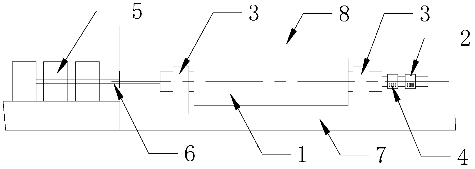
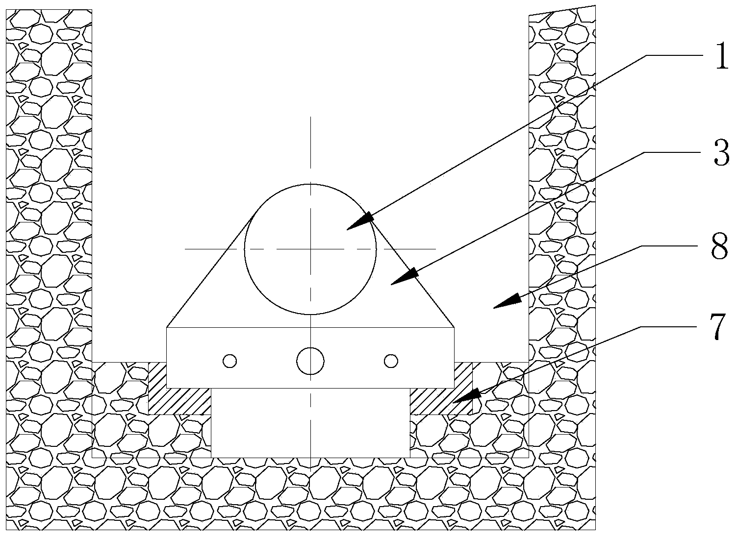
[0041] A low-speed rotating electric heating process for a turbogenerator rotor 1 dynamic balance test. Its process steps are as follows:

[0042] 1) When the turbogenerator rotor 1 is undergoing a dynamic balance test in the manufacturing plant, a low-speed rotating electric heating process is used to complete the thermal aging test of the rotor 1;

[0043] 2) When the turbine generator rotor 1 rotates electrically at low speed, the test brush holder 4 is used to provide the excitation current for heating to the rotor collector ring 2;

[0044] 3) When the turbine generator rotor 1 rotates at a low speed and is electrically heated, the rotor 1 rotates at the speed of the barring machine 6:

[0045] 4) When the rotor 1 of the turbogenerator rotates at a low speed and is electrically heated, for a drive system with a lower minimum speed of the drive motor 5, the rotor 1 can also drive the motor 5 to rotate at a minimum speed;

[0046] 5) When the turbine generator rotor 1 rot...


PUM


Abstract

The invention relates to a low-speed rotating electric heating technology for a steam-turbine generator rotor in a dynamic balance test. By adopting the technology, the target of finishing a thermal aging test by heating a rotor is achieved by feeding exciting current into a low-speed rotation rotor, the effect of rotor deflection is overcome by rotation of the rotor, the effect on test equipment and the like caused by a rotary magnetic field is neglected by controlling the rotation speed, heating of the rotor by a simple and practical method is finally achieved, and the condition that the effect of heating the rotor meets all requirements is ensured.

Description

Technical field: [0001] The invention relates to a low-speed rotating electric heating process during a dynamic balance test of a steam turbine generator rotor. Background technique: [0002] During the dynamic balance test of the turbogenerator rotor (1), the thermal aging test of the rotor (1) is required. It is to ensure that the rotor (1) rotates for a period of time to achieve the purpose of aging when the temperature and speed of the rotor (1) meet the requirements. In order to achieve the purpose of thermal aging of the rotor (1), there are two types of process methods, one is to heat the rotor (1) to the required temperature and then increase the speed to the rated speed, and the other is to increase the speed of the rotor (1) to the rated speed Reheat the rotor (1) to the required temperature. [0003] Currently available rotor (1) heating processes include: [0004] 1) Static electric heating process, the rotor (1) is heated by exciting current at rest until the...

Claims


Application Information

Patent Timeline
Patent Type & Authority Applications(China)
IPC IPC(8): G01M1/16
Inventor 刘俊英刘昱光张春莉韩继敏王恒孟秋
Owner HARBIN ELECTRIC MASCH CO LTD
Learn More