
Connecting device for U-shaped steel bracket

A technology of connecting device and section steel, which is used in shaft equipment, shaft lining, mining equipment, etc., can solve the problems of damage to the support body, the collapse of the cable connection, and the easy breakage of the curved beam, so as to avoid connection failure, The effect of ensuring connection stability

Inactive Publication Date: 2014-05-28
LIAONING TECHNICAL UNIVERSITY
View PDF6 Cites 2 Cited by
  • Summary
  • Abstract
  • Description
  • Claims
  • Application Information

AI Technical Summary

Problems solved by technology

When rock burst occurs, the damaged surrounding rock will have a violent impact on the support body, causing the load on the support body to increase suddenly, exceeding the static pressure by several times, ten times or even greater, often causing the support body to burst. local damage, deformation or overall collapse damage, which poses a serious threat to the safety of underground workers and production equipment
[0003] At present, the most widely used roadway support is U-shaped steel support, which is mostly composed of three-section, four-section or six-section arc-shaped beams overlapping each other, and forms an arch support or a ring support ring. The two adjacent curved beams are simply hooped by the clamp cable, but this connection method leads to very poor connection stability. Once the impact of ground pressure occurs, the part of the curved beam is easy to break or the clamp cable connection collapses, and eventually Lead to the overall collapse of the support and support failure, resulting in safety accidents

Method used


Image

  • Connecting device for U-shaped steel bracket
  • Connecting device for U-shaped steel bracket
  • Connecting device for U-shaped steel bracket

Examples


Embodiment Construction

[0016] The present invention will be further described in detail below in conjunction with the accompanying drawings and specific embodiments.

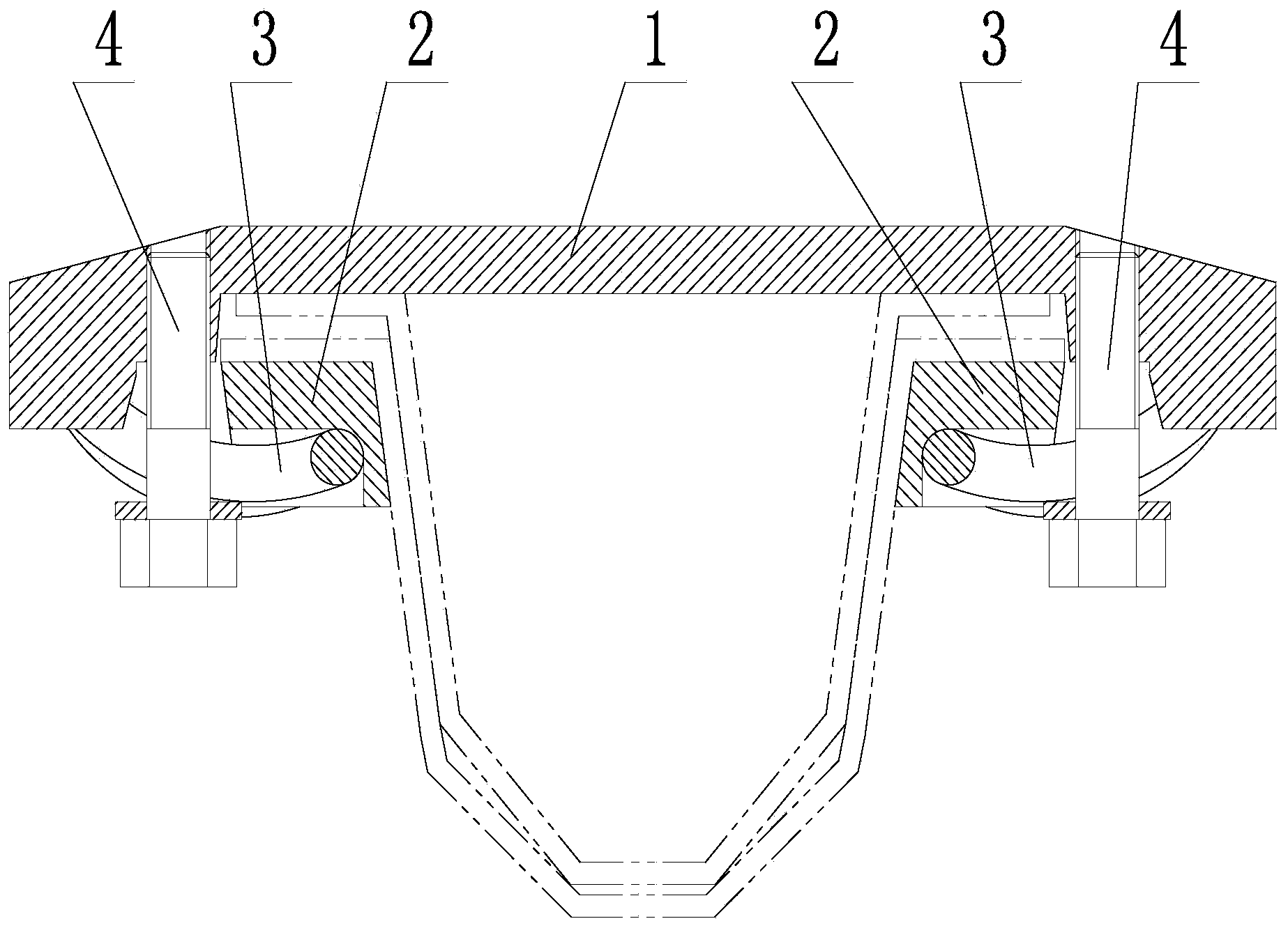
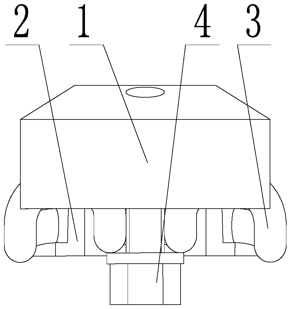
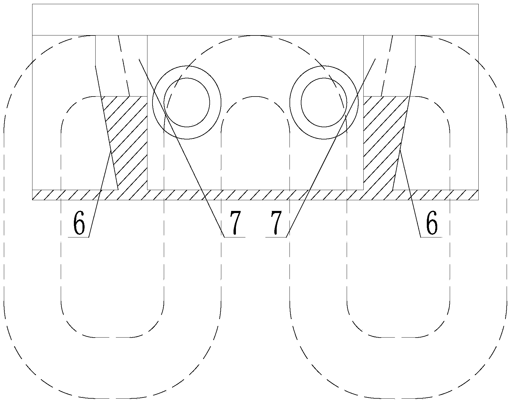
[0017] like figure 1 , 2 , 3, a connecting device for a U-shaped steel bracket, including a top cover 1, a base 2 and a W-shaped elastic fastener 3, the top cover 1 corresponds to the outer side arc beam, and the base 2 corresponds to the inner side arc beam. The side arc beam corresponds; the top of the W-shaped elastic fastener 3 corresponds to the base 2, the tail end of the W-shaped elastic fastener 3 corresponds to the top cover 1, and the W-shaped elastic fastener 3 passes through the lock. Tight bolt 4 is fixed on the top cover 1.

[0018] Two slopes 6 are arranged on the base 2, and the two slopes 6 are arranged symmetrically, and limit holes 7 are arranged at the ends of the two slopes 6; It is a hook structure, and the limit hole 7 corresponds to the hook structure at the end of the arm of the W-shaped elastic fastener 3 ...


PUM


Abstract

A connecting device for a U-shaped steel bracket belongs to the technical field of coal mine tunnel supporting. The connecting device comprises a top cover, a base and a W-shaped elastic strip fastener, wherein the top cover is corresponding to an outer lapping side arc-shaped beam, the base corresponds to an inner lapping side arc-shaped beam, the top end of the W-shaped elastic strip fastener corresponds to the base, the tail end of the W-shaped elastic strip fastener corresponds to the top cover, and the W-shaped elastic strip fastener is fixed on the top cover through a bolt. Two slopes are arranged on the base and are symmetrically arranged, and a limiting hole is formed in the tail end of each slope; the end parts of two supporting arms of the W-shaped elastic strip fastener are set to be of hook-shaped structures which correspond to the limiting holes. According to the invention, the traditional clamp cable connecting method is abandoned, the W-shaped elastic strip fastener is adopted as a limiting member and composure control is realized through the W-shaped elastic strip fastener, when compact ground pressure is encountered, the movement of two sets of connecting devices along with the respective arc-shaped beams fixedly connected with the two sets of connecting devices is realized in the mutual diastrophism process of the two adjacent arc-shaped beams, and the failure of connection at the connecting part of the two adjacent arc-shaped beams is avoided, so that the stability of connection is guaranteed.

Description

technical field [0001] The invention belongs to the technical field of coal mine roadway support, in particular to a connecting device for a U-shaped steel support. Background technique [0002] my country's energy structure is still dominated by coal consumption, and most of my country's coal resources are buried in the depths below a kilometer, so it is an inevitable trend for coal mining to go deep. But at the same time, deep mining brings serious underground disasters. As one of the major dynamic disasters in coal mines, rock burst has caused a large number of property losses and casualties in recent years. When rock burst occurs, the damaged surrounding rock will have a violent impact on the support body, causing the load on the support body to increase suddenly, exceeding the static pressure by several times, ten times or even greater, often causing the support body to burst. Local damage, deformation or overall collapse and damage have caused serious threats to the ...

Claims


Application Information

Patent Timeline
IPC IPC(8): E21D11/22
Inventor 阎海鹏肖永惠潘一山李忠华李国臻
Owner LIAONING TECHNICAL UNIVERSITY
Learn More