Data card and its multi-mode broadband antenna system
An antenna system and broadband antenna technology, applied in the field of data cards, can solve the problems of data cards and cover the full frequency band of LTE, etc.
- Summary
- Abstract
- Description
- Claims
- Application Information
AI Technical Summary
Problems solved by technology
Method used
Image

Examples
Embodiment 1
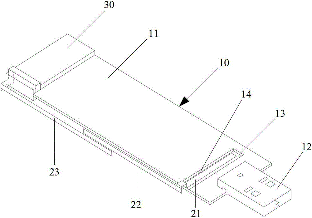
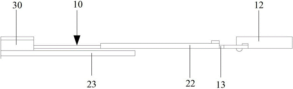
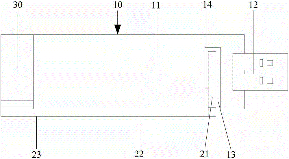
[0038] like figure 1 As shown, the multi-mode broadband antenna system for a data card provided by an embodiment of the present invention includes a PCB board 10 , and a first radiator 21 , a second radiator 22 and a third radiator 23 in a strip shape.
[0039] One side of the PCB board 10 is covered with a metal ground 11, and the USB plug 12 of the data card is arranged on a short side of the PCB board 10; a long side of the PCB board 10 close to the USB plug 12 is provided with a first radiator for accommodating a first radiator 21 of the groove 13. In this embodiment, the first radiator 21 is strip-shaped, and the groove 13 is also strip-shaped, which is compatible with the first radiator 21 .
[0040] The first radiator 21 is located in the groove 13 and is connected to the transceiver module (not shown in the figure) of the data card through the feeder 14 . The first end of the first radiator 21 is located at the bottom of the groove 13 , and the second end of the firs...
Embodiment 2
[0055] This embodiment is basically the same as Embodiment 1, such as Figure 5 and Image 6 As shown, the first radiator 21 is located in the groove 13 of the PCB board 10 , and the first end of the second radiator 22 is electrically connected to the second end of the first radiator 21 at the edge of the PCB board 10 . The second end of the second radiator 22 is coupled and connected to the first end of the third radiator 23 in the form of a slot. After the second end of the third radiator 23 is bent, it bypasses the plastic bracket 30 in the data card and connects with the One end of the metal ground 11 away from the USB plug 12 is electrically connected.
[0056] The difference between this embodiment and Embodiment 1 is that the second radiator 22 and the third radiator 23 are located on the same horizontal plane, and the second end of the second radiator 22 is connected to the third radiator 23 through a bent portion. A gap is formed at the first end of the , resulting ...
Embodiment 3
[0059] This embodiment is basically the same as Embodiment 1, such as Figure 7 , Figure 8 and Figure 9 As shown, the first radiator 21 is located in the groove 13 of the PCB board 10 , and the first end of the second radiator 22 is electrically connected to the second end of the first radiator 21 at the edge of the PCB board 10 . After the second end of the third radiator 23 is bent, it bypasses the plastic bracket 30 in the data card and is electrically connected to the end of the metal ground 11 away from the USB plug 12 .
[0060] The difference between this embodiment and Embodiment 1 is that the second radiator 22 and the third radiator 23 are disposed on the long sides of the groove 13 of the PCB board 10 . The second radiator 22 is located on the front side of the PCB board 10 , the third radiator 23 is located on the back side of the PCB board 10 , the second end of the second radiator 22 and the first end of the third radiator 23 are located on two sides of the P...
PUM
 Abstract
Description
Claims
Application Information
 - R&D
- Intellectual Property
- Life Sciences
- Materials
- Tech Scout
- Unparalleled Data Quality
- Higher Quality Content
- 60% Fewer Hallucinations
Browse by: Latest US Patents, China's latest patents, Technical Efficacy Thesaurus, Application Domain, Technology Topic, Popular Technical Reports.
© 2025 PatSnap. All rights reserved.Legal|Privacy policy|Modern Slavery Act Transparency Statement|Sitemap|About US| Contact US: help@patsnap.com