
Adjustable position fixing installation device of soil pressure gauge

An earth pressure gauge and installation device technology, which is applied in the field of foundation soil survey, construction, infrastructure engineering, etc., can solve the problem of difficulty in keeping the surface of the earth pressure gauge flush with the surface of the concrete structure, low reliability, and impact on the progress of the project construction period. and other problems, to achieve the effect of improving the accuracy and precision of monitoring data, good protection and safety, and wide engineering applicability

Active Publication Date: 2014-05-21
NANJING HYDRAULIC RES INST
View PDF5 Cites 11 Cited by
  • Summary
  • Abstract
  • Description
  • Claims
  • Application Information

AI Technical Summary

Problems solved by technology

[0004] (1) The construction of the interface installation of the earth pressure gauge takes a long time
In the traditional pre-embedded method, the earth pressure gauge itself has no fixing device, and it needs to be connected to the structural steel bar by binding or welding, and the installation position is adjusted in real time according to the thickness of the concrete cover. Therefore, it takes a long time to bury an earth pressure gauge. time
Especially for large concrete structures that need to bury more earth pressure gauges, more construction time will be required, which will affect the progress of the entire project
[0005] (2) The reliability of the interface installation of the earth pressure gauge is low
[0006] (3) The accuracy of the monitoring data of the earth pressure gauge is poor
In the traditional pre-embedding method, it is often difficult to keep the surface of the earth pressure gauge flush with the surface of the concrete structure after the earth pressure gauge is buried, leaving a large gap between the two. It is covered with a thick layer of concrete, and the obtained monitoring data cannot truly reflect the force of the interface earth pressure, which makes the accuracy and reliability of the monitoring data poor

Method used


Image

  • Adjustable position fixing installation device of soil pressure gauge
  • Adjustable position fixing installation device of soil pressure gauge
  • Adjustable position fixing installation device of soil pressure gauge

Examples


Embodiment 1

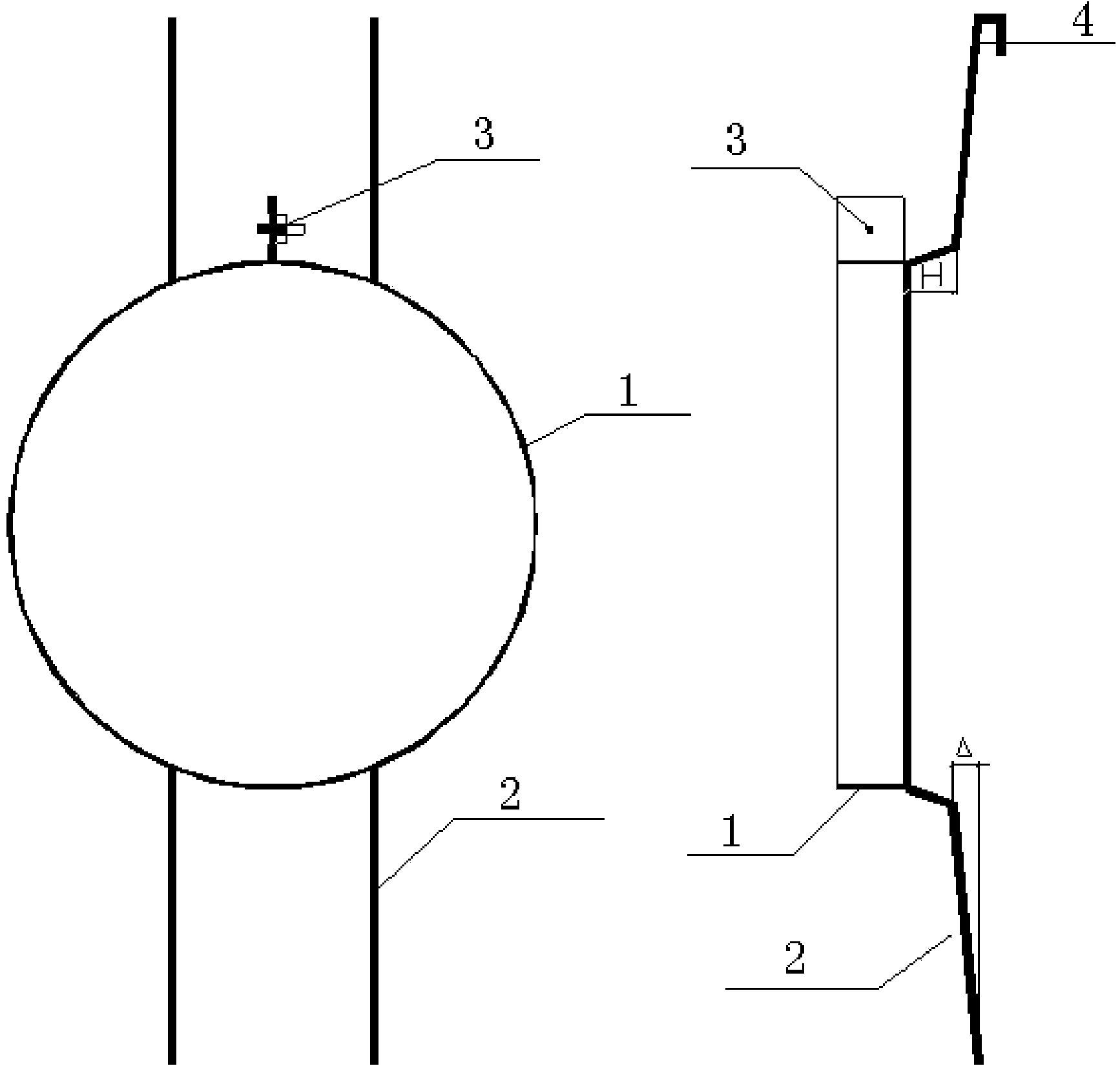
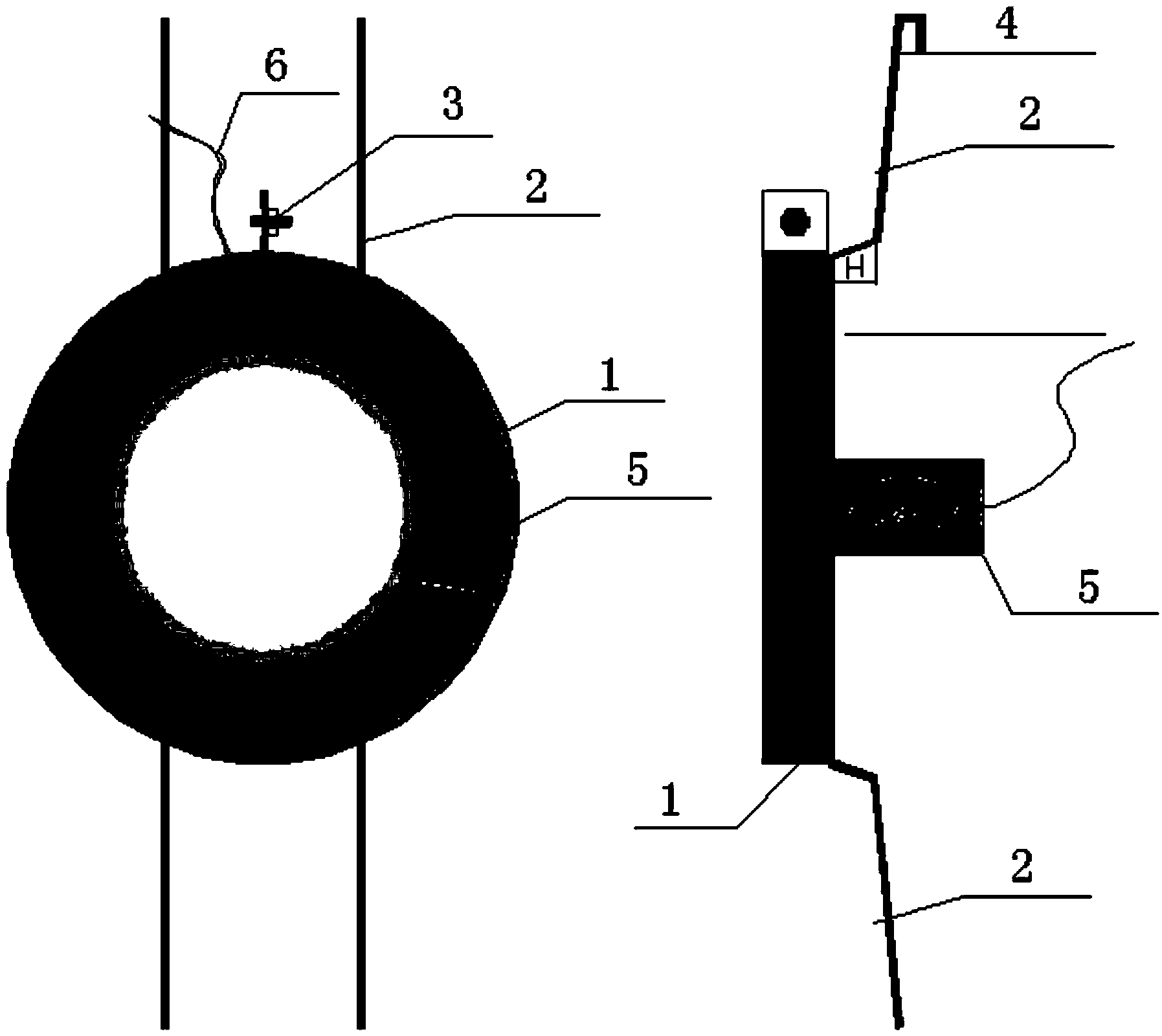
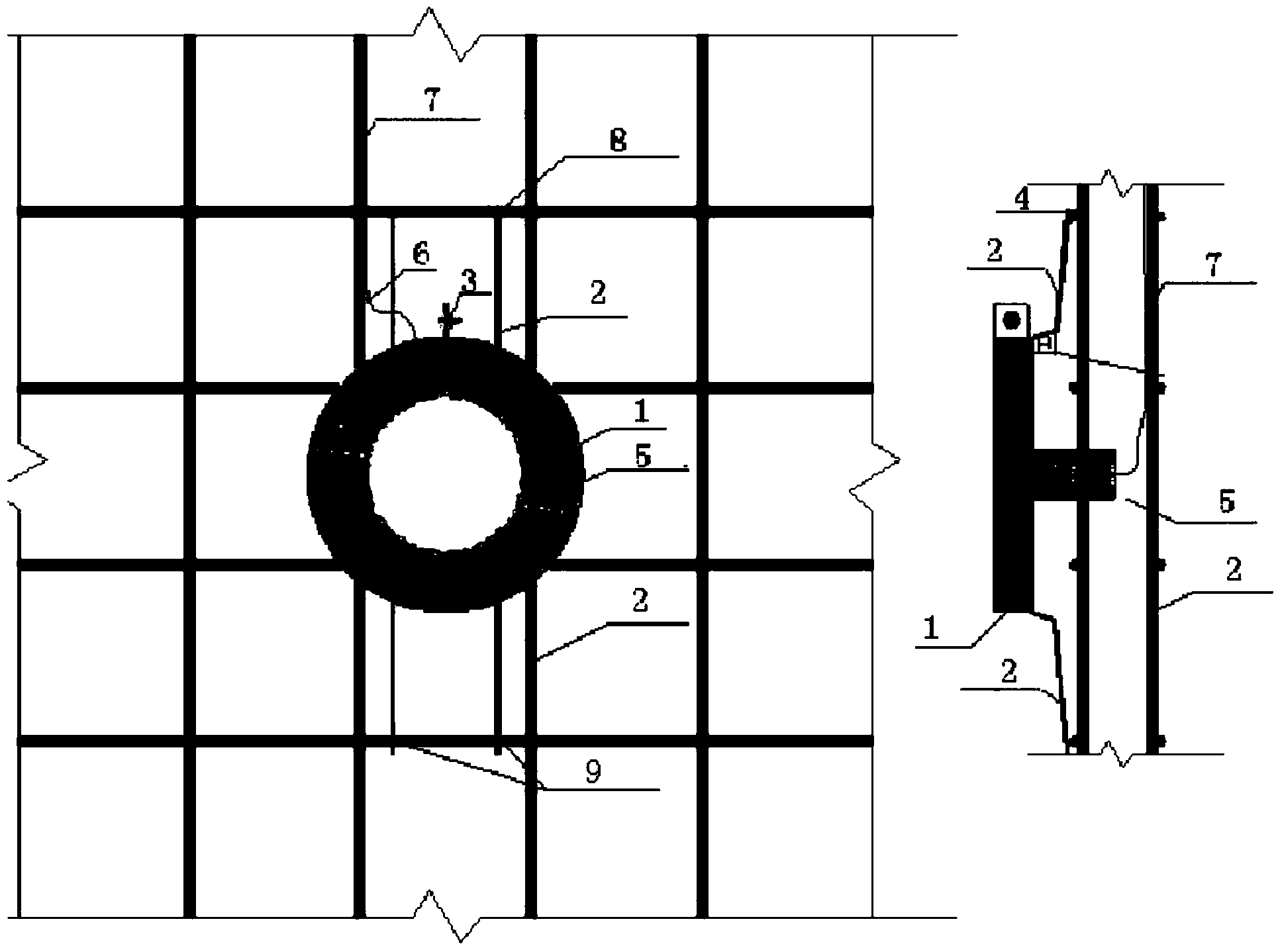
[0032] Embodiment 1, according to the appearance size of the earth pressure gauge, a thin steel plate with a thickness of 1 to 2 mm is used as the hoop 1, and the width of the thin steel plate is the same as the thickness of the earth pressure gauge 5 or slightly smaller than the thickness of the earth pressure gauge (to ensure that the surface of the earth pressure gauge is flush with the hoop or slightly protruding from the hoop to prevent the hoop from affecting the contact between the soil and the earth pressure gauge), process the hoop according to the shape of the earth pressure gauge (the earth pressure gauge in this implementation is round), so that the hoop encloses the earth pressure gauge, Drill screw holes at the joints at both ends of hoop 1 and fix them with screws 3 (such as Figure 2-1 , Figure 2-2 shown). Weld two crotch steel bars (fixed steel bars) 2 at each 1 / 3 of the back of hoop 1, the size of crotch 4 is slightly larger than the diameter of the structura...


PUM


Abstract

An adjustable position fixing installation device of a soil pressure gauge is arranged on the periphery of the soil pressure gauge and characterized in that a hoop made of a rigid plate is arranged on the adjustable position fixing installation device, the thickness of the loop is equal to or smaller than that of the soil pressure gauge, the shape of the hoop corresponds to the shape of the periphery of the soil pressure gauge, and the size of the inside of the hoop is equal to or slightly greater than the dimension of the periphery of the soil pressure gauge. Two fixing reinforcing steel bars are fixed on the back surface of the hoop, hooks are arranged on ends of the two fixing reinforcing steel bars, and other ends of the fixing reinforcing steel bars incline to the direction of the back surface. By means of the adjustable position fixing installation device of the soil pressure gauge, interface type installation of the soil pressure gauge can be achieved conveniently and accurately, and the problem that the soil pressure gauge is easily covered with concrete when buried is solved, installation time is saved further, the 'survival rate' of the soil pressure gauge is increased, and installation cost is reduced. Furthermore, the adjustable position fixing installation device of the soil pressure gauge is an ideal device capable of overcoming the shortcoming in the prior art and has obvious economic benefit and social benefit.

Description

technical field [0001] The invention belongs to the field of earth pressure testing in in-situ observation of geotechnical engineering, and particularly relates to the monitoring of the influence of soil on the deformation and stability of large concrete structures in complex and changeable environments such as oceans and underground spaces, and can be used for the interface type of earth pressure gauges. Install and improve the accuracy of earth pressure gauge monitoring data. Background technique [0002] With the continuous improvement of my country's economic status in the development of global production, and at the same time meeting the adjustment of national development strategies and the requirements for a substantial increase in port capacity, my country's port construction has developed towards a large-scale and deep-water pattern in recent years. However, there are a large number of deep soft soil layers with poor physical and mechanical indicators in the coastal ...

Claims


Application Information

Patent Timeline
Patent Type & Authority Applications(China)
IPC IPC(8): E02D1/00
Inventor 王伟蔡正银杨立功周俊同曹永勇黄英豪关云飞高自兵李武方绪顺刘守华武颖利
Owner NANJING HYDRAULIC RES INST
Learn More