A frameless display device
A display device and borderless technology, which is applied in nonlinear optics, instruments, optics, etc., can solve problems such as unreasonable connection structure of connectors, existence of reliability, and influence on the overall strength of liquid crystal display panels.
- Summary
- Abstract
- Description
- Claims
- Application Information
AI Technical Summary
Problems solved by technology
Method used
Image
Examples
Embodiment 1
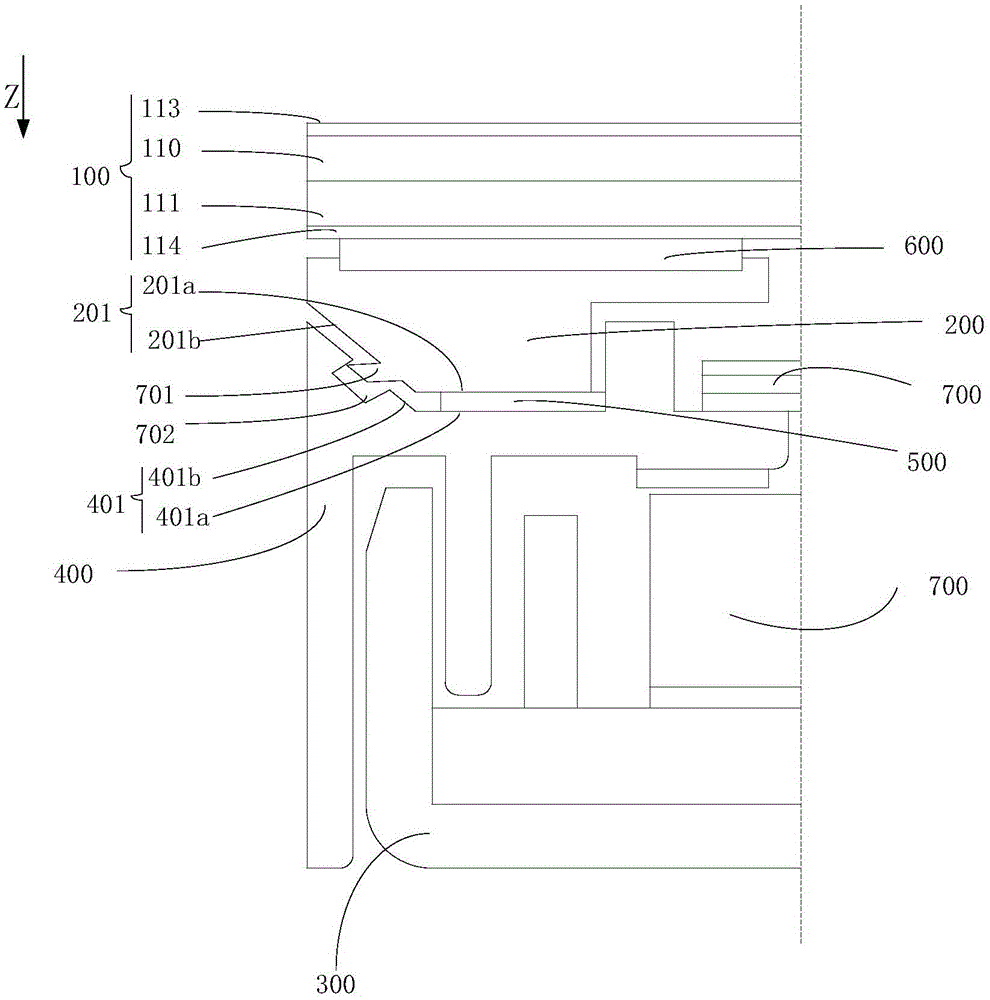
[0051] figure 2 Shown is a schematic diagram of a first embodiment of the present invention.
[0052] like figure 2 As shown, in this embodiment, the borderless display device includes a display panel 100, a panel connector 200 and a backlight, wherein the display panel 100 includes a display surface and a back surface opposite to the display surface, and the panel connector 200 One end of which is fixed on the peripheral area of the back of the display panel 100, the other end of the panel connector 200 is formed with a first support surface 201 for supporting the display panel 100, and the first support surface 201 is formed with The first buckle part, the display panel 100 and the panel connector 200 together form a display panel 100 module;
[0053] The backlight module includes a back plate 300, a plastic frame 400 and an optical assembly 700, the back plate 300 and the plastic frame 400 are both arranged on the back side of the display panel 100, and the optical as...
Embodiment 2
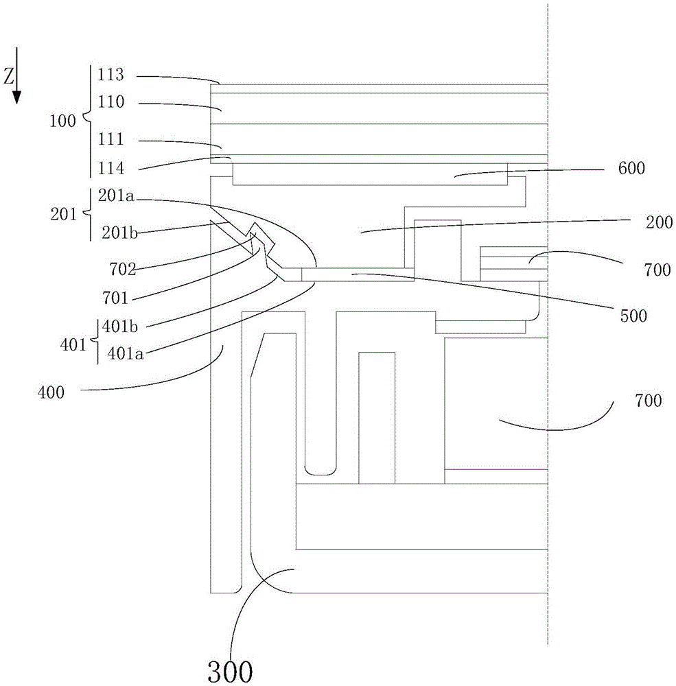
[0061] image 3 Shown is a schematic diagram of a second embodiment of the present invention.
[0062] like image 3 As shown, the present embodiment is the same as Embodiment 1 in that they both use the cooperation of the hook 701 and the hook groove 702 to realize the engagement and fixation of the panel connector 200 and the plastic frame 400, and both adopt the cooperation of an inclined plane to realize the engagement. Guiding and positioning function in the assembly process; the only difference between this embodiment and Embodiment 1 is that in this embodiment, the first buckle part includes an inwardly recessed hook groove formed on the first support surface 201 702, the second buckle part includes a hook 701 protruding on the second support surface 401, and the hook 701 can apply a pressing force to the display panel 100 toward the back plate 300 , elastically deformed to be fixed in the hook groove 702 by snapping.
Embodiment 3
[0064] Figure 4 Shown is a schematic diagram of a third embodiment of the present invention.
[0065] The difference between this embodiment and Embodiment 1 is that in this embodiment, the first buckle part and the second buckle part are matched in a button-type fastening manner. specifically,
[0066] like Figure 4 As shown, in this embodiment, the first buckle part includes an insert formed on the first supporting surface 201, and the insert includes an insert connected to the first supporting surface 201 and moves away from the first supporting surface 201. an extension 801a extending in the direction of the display panel 100; and a head 801b connected to the end of the extension 801a away from the display panel 100;
[0067] The second buckle portion includes an accommodating space 803 for accommodating the head 801 b through the insertion hole 802 formed on the second support surface 401 and the insertion hole 802 .
[0068] In the technical solution provided in th...
PUM
 Abstract
Description
Claims
Application Information
 - R&D
- Intellectual Property
- Life Sciences
- Materials
- Tech Scout
- Unparalleled Data Quality
- Higher Quality Content
- 60% Fewer Hallucinations
Browse by: Latest US Patents, China's latest patents, Technical Efficacy Thesaurus, Application Domain, Technology Topic, Popular Technical Reports.
© 2025 PatSnap. All rights reserved.Legal|Privacy policy|Modern Slavery Act Transparency Statement|Sitemap|About US| Contact US: help@patsnap.com


