
Three-dimensional movable compacted sand pile forming system in centrifugal test

A technology of compacted sand pile and centrifugal test, which is applied in the test of foundation structure, sheet pile wall, building, etc., can solve problems such as insufficient understanding and application constraints of compacted sand pile composite foundation, and achieve fast piling speed and production Convenience and high efficiency

Inactive Publication Date: 2015-07-29
TONGJI UNIV +1
View PDF6 Cites 0 Cited by
  • Summary
  • Abstract
  • Description
  • Claims
  • Application Information

AI Technical Summary

Problems solved by technology

However, the current domestic engineering circles do not have a thorough understanding and mastery of the design and calculation theory, construction technology and parameters, construction quality control and detection methods of the compacted sand pile composite foundation, and the application of the compacted sand pile composite foundation has been greatly affected. constraints

Method used


Image

  • Three-dimensional movable compacted sand pile forming system in centrifugal test
  • Three-dimensional movable compacted sand pile forming system in centrifugal test
  • Three-dimensional movable compacted sand pile forming system in centrifugal test

Examples


Embodiment 1

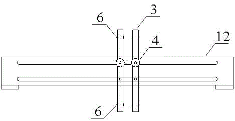
[0021] The device consists of a sleeve 1 and a piston 2 required for piling, a set of pulleys 6 located on the left and right sides of the sleeve to ensure that the sand pile is vertical, a chute 12 for the pulley to move above the model box, and a hand-operated piling weight composition.

[0022] Sleeve 1 is an aluminum hollow cylinder with a wall thickness of 2 mm. The length and outer diameter must be determined according to the length and diameter of the target sand pile. small. Piston 2 is a cylindrical iron long rod with a diameter of 8mm. The diameter of the 10mm at the bottom end of the rod is expanded to be slightly smaller than the inner diameter of the sleeve, which is used to hit the sand downwards, and the diameter of the 5mm at the top is enlarged to 30mm. Accept the downward impact force of the piling weight.

[0023] The pulley assemblies positioned at both sides of the sleeve 1 to ensure the verticality of the sand piles include four pulleys 6, two on the le...


PUM


Abstract

The invention relates to a three-dimensional movable SCP forming system in a centrifugal test. The system is composed of a sleeve, a piston, sliding wheel assemblies and a hand-powered heavy piling hammer, wherein the sleeve and the piston are needed in the piling process. The sleeve is a hollow cylinder. The piston is a cylindrical rod. The verticality of the sleeve which is clamped in the middle is guaranteed through four sliding wheelslocated on the two sides of the sleeve. Sliding chutes can be connected with a model box used in the test through bolts at the two ends and are fixed above the model box. The hand-powered heavy piling hammer is composed of an upper hand-powered structure and lower guide rails. The upper hand-powered structure can drive the heavy hammer to reciprocate upwards and downwards by shaking a handle of the upper hand-powered structure, so that the heavy hammer strike the top of the piston downwards, and sand is compacted through the piston; meanwhile, a wheel at the top of the upper hand-powered structure is rotated, so that the heavy hammer and a linkage structure of the heavy hammer move upwards and downwards, and the position is adjusted. The lower guide rails comprise two sets of guide rails which are mutually perpendicular on the horizontal plane. The upper hand-powered structure can slide freely in the direction of two guide rails. According to the three-dimensional movable SCP forming system, the SCP forming process can be really simulated in the centrifugal model test; the three-dimensional movable SCP forming system is not only convenient to use and efficient, but also capable of guaranteeing verticality, continuity, compactness and the like of a sand pile, thereby being capable of well providing service for relevant research work.

Description

technical field [0001] The invention belongs to the research field of offshore compacted sand pile (SCP) composite foundation, and in particular relates to a three-dimensional movable compacted sand pile forming system that can be applied in centrifugal model tests. Background technique [0002] With the rapid development of the global economy and container transportation industry, it has become an inevitable development trend for seaport terminals to develop into offshore, open and deep waters. With the construction of ports in the open sea, the construction of projects such as artificial islands is gradually advancing to deeper waters, and foundation reinforcement has become an indispensable construction technology in transportation construction such as port construction in the open sea. In order to deal with the soft ground under water, various ground treatment techniques must be used extensively. Compared with the traditional foundation treatment method, the compacted s...

Claims


Application Information

Patent Timeline
Patent Type & Authority Patents(China)
IPC IPC(8): E02D11/00E02D33/00
Inventor 马险峰时蓓玲张曦马振江何蔺荞张晨龙赵晓琴
Owner TONGJI UNIV
Learn More