
Novel gate lifting device

A gate, a new type of technology, applied in water conservancy projects, marine engineering, coastline protection and other directions, can solve the problems of poor contact, high cost, high failure rate, and achieve the effect of reducing the incidence of failures, reducing production costs, and working stably

Inactive Publication Date: 2014-05-14
YANGZHOU JIUDE HEAVY IND TECH
View PDF0 Cites 6 Cited by
  • Summary
  • Abstract
  • Description
  • Claims
  • Application Information

AI Technical Summary

Problems solved by technology

[0002] At present, most of the existing gate lifting devices are carbon brush lifting devices, and the carbon brush materials of the electric carbon brush lifting device are divided into copper and cast iron. After a long period of use, the carbon brush material is expensive if copper alloy is used, such as Cast iron is easy to rust, resulting in poor contact and open circuit, with a high failure rate

Method used


Image

  • Novel gate lifting device

Examples


Embodiment Construction

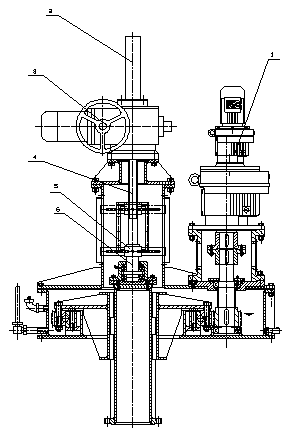
[0008] A new gate lifting device, the lifting device includes a reduction mechanism 1, a shield 2, an electric actuator 3, a transmission screw 4 and a lifting mechanism, the reduction mechanism 1 is connected with the lifting device, and the upper part of the lifting device Connect the electric actuator 3 and the shield 2 in sequence, the lifting mechanism includes a screw 6 and a nut 5, one end of the transmission screw 4 is connected with the electric actuator 3, and the other end is connected with the screw 6, the The nut 5 is arranged outside the screw rod 6 .


PUM


Abstract

The invention relates to a novel gate lifting device which comprises a speed reducing mechanism, a protection cover, a motor-driven execution mechanism, a transmission screw and a lifting mechanism. The speed reducing mechanism is connected with the lifting device, the upper portion of the lifting device is sequentially connected with the motor-driven execution mechanism and the protection cover, the lifting mechanism comprises a screw and a nut, one end of the transmission screw is connected with the motor-driven execution mechanism, the other end of the transmission screw is connected with the screw, and the nut is arranged on the outside of the screw. The novel gate lifting device is simple in structure and stable in work, utilizes a screw nut transmission mechanism to replace a motor-driven carbon brush device, achieves a spindle lifting function, eliminates the behindhand carbon brush structure, reduces production cost, and reduces device fault rate.

Description

technical field [0001] The invention relates to a novel gate lifting device. Background technique [0002] At present, most of the existing gate lifting devices are carbon brush lifting devices, and the carbon brush materials of the electric carbon brush lifting device are divided into two types: copper and cast iron. Cast iron is easy to rust and cause poor contact and open circuit, and the failure rate is higher. Contents of the invention [0003] In order to solve the above problems, the present invention provides a novel gate lifting device with simple structure, low production cost and low failure rate. [0004] The technical solution of the present invention is: the lifting device includes a deceleration mechanism, a shield, an electric actuator, a transmission screw and a lifting mechanism, the deceleration mechanism is connected with the lifting device, and the upper part of the lifting device is connected with an electric motor in sequence. The actuator and the ...

Claims


Application Information

Patent Timeline
Patent Type & Authority Applications(China)
IPC IPC(8): E02B7/20E02B7/36
Inventor 李伟
Owner YANGZHOU JIUDE HEAVY IND TECH
Learn More