
Laser cutting table

A laser and cutting machine technology, applied in the cutting machine field, can solve the problems of affecting cutting quality, affecting cutting quantity, low work efficiency, etc., and achieve the effect of improving cutting precision, improving cutting efficiency and simple structure

Inactive Publication Date: 2014-05-14
WUJIANG JIAYUN TEXTILE FINISHING
View PDF7 Cites 2 Cited by
  • Summary
  • Abstract
  • Description
  • Claims
  • Application Information

AI Technical Summary

Problems solved by technology

[0003] Laser cutting machines are widely used in clothing and luggage industries. In order to ensure the cutting quality, the laser head needs to be kept on the same level during laser cutting. The existing laser cutting machines have a small worktable, so the work efficiency is not high, especially When cutting some large-format fabrics, the disadvantages of the existing laser cutting machine are obvious. The existing cutting bed has a small working surface, and the number of cuttings in one working stroke of the laser cutting machine is small. It needs to re-load the material, and there needs to be a waiting time during the feeding process. Therefore, the waiting time per unit time will be too long, which will affect the cutting quantity. In addition, when large-area fabrics need to be cut, the existing The worktable is small, and it cannot be cut on one worktable at one time. It needs to be cut several times and cut in batches, which will not only affect the efficiency but also affect the cutting quality.

Method used


Image

  • Laser cutting table

Examples


Embodiment Construction

[0016] The present invention will be further explained below in conjunction with the accompanying drawings and specific embodiments. It should be understood that the following specific embodiments are only used to illustrate the present invention and are not intended to limit the scope of the present invention. It should be noted that the words "front", "rear", "left", "right", "upper" and "lower" used in the following description refer to the directions in the drawings, and the words "inner" and "outer ” refer to directions towards or away from the geometric center of a particular part, respectively.

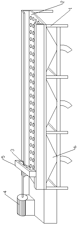
[0017] Such as figure 1 As shown, the laser cutting bed disclosed in the present invention includes a motor, a frame 1, a workbench 2, a discharge rubber roller, a feed rubber roller, a mesh belt, a tension adjustment device, a laser cutting device 3, a servo motor 4 and a moving Mechanism 5, the laser cutting device 3 is arranged on the frame 1 through the moving mechanism 5,...


PUM


Abstract

The invention discloses a laser cutting table which comprises a motor, a frame, a workbench, a discharge rubber roll, a feed rubber roll, a mesh belt, a tension adjusting device, a laser cutting device, a servo motor and a moving mechanism. The laser cutting device is disposed on the frame through the moving mechanism. The servo motor is disposed below the frame. The drive end of the servo motor is connected with the moving mechanism. The laser cutting table is simple in structure and convenient to use, the laser cutting device can be driven by the servo motor to move freely, the cutting area and flexibility of the cutting table are increased effectively, and cloth cutting efficiency and fineness are increased.

Description

[0001] technical field [0002] The invention relates to a cutting bed, in particular to a laser cutting bed. Background technique [0003] Laser cutting machines are widely used in clothing and luggage industries. In order to ensure the cutting quality, the laser head needs to be kept on the same level during laser cutting. The existing laser cutting machines have a small worktable, so the work efficiency is not high, especially When cutting some large-format fabrics, the disadvantages of the existing laser cutting machine are obvious. The existing cutting bed has a small working surface, and the number of cuttings in one working stroke of the laser cutting machine is small. It needs to re-load the material, and there needs to be a waiting time during the feeding process. Therefore, the waiting time per unit time will be too long, which will affect the cutting quantity. In addition, when large-area fabrics need to be cut, the existing The worktable is small, and it can...

Claims


Application Information

Patent Timeline
Patent Type & Authority Applications(China)
IPC IPC(8): D06H7/22
Inventor 陈玉林
Owner WUJIANG JIAYUN TEXTILE FINISHING
Learn More