
Anti-creeping energy absorption device for railway vehicle

An energy-absorbing device and a technology for rail vehicles, which are used in railway vehicle wheel guards/buffers, transportation and packaging, railway vehicle body parts, etc. Easy to roll over or overturn and other problems, to prevent vertical instability, significant energy absorption effect, and prevent deflection

Inactive Publication Date: 2014-05-14
CRRC QINGDAO SIFANG CO LTD
View PDF10 Cites 32 Cited by
  • Summary
  • Abstract
  • Description
  • Claims
  • Application Information

AI Technical Summary

Problems solved by technology

[0004] At present, the anti-climbing devices installed on domestic rail vehicles generally adopt the method of tailor-welded steel plates. If the strength of this type of anti-climbing devices is too high, when the train hits, the impact force will be transmitted to the bottom frame only, reducing the force-bearing area. , so that the impact energy cannot be fully absorbed, and the vehicle is prone to rollover or overturning. If the strength is insufficient, it will be easily affected by the vertical load, resulting in vertical instability, which will still cause consequences such as vehicle climbing. Therefore, the existing anti-climbing The device needs to be further improved in terms of strength characteristics and crash performance

Method used


Image

  • Anti-creeping energy absorption device for railway vehicle
  • Anti-creeping energy absorption device for railway vehicle
  • Anti-creeping energy absorption device for railway vehicle

Examples


Embodiment Construction

[0025] Below in conjunction with accompanying drawing and specific embodiment the present invention is described in further detail:

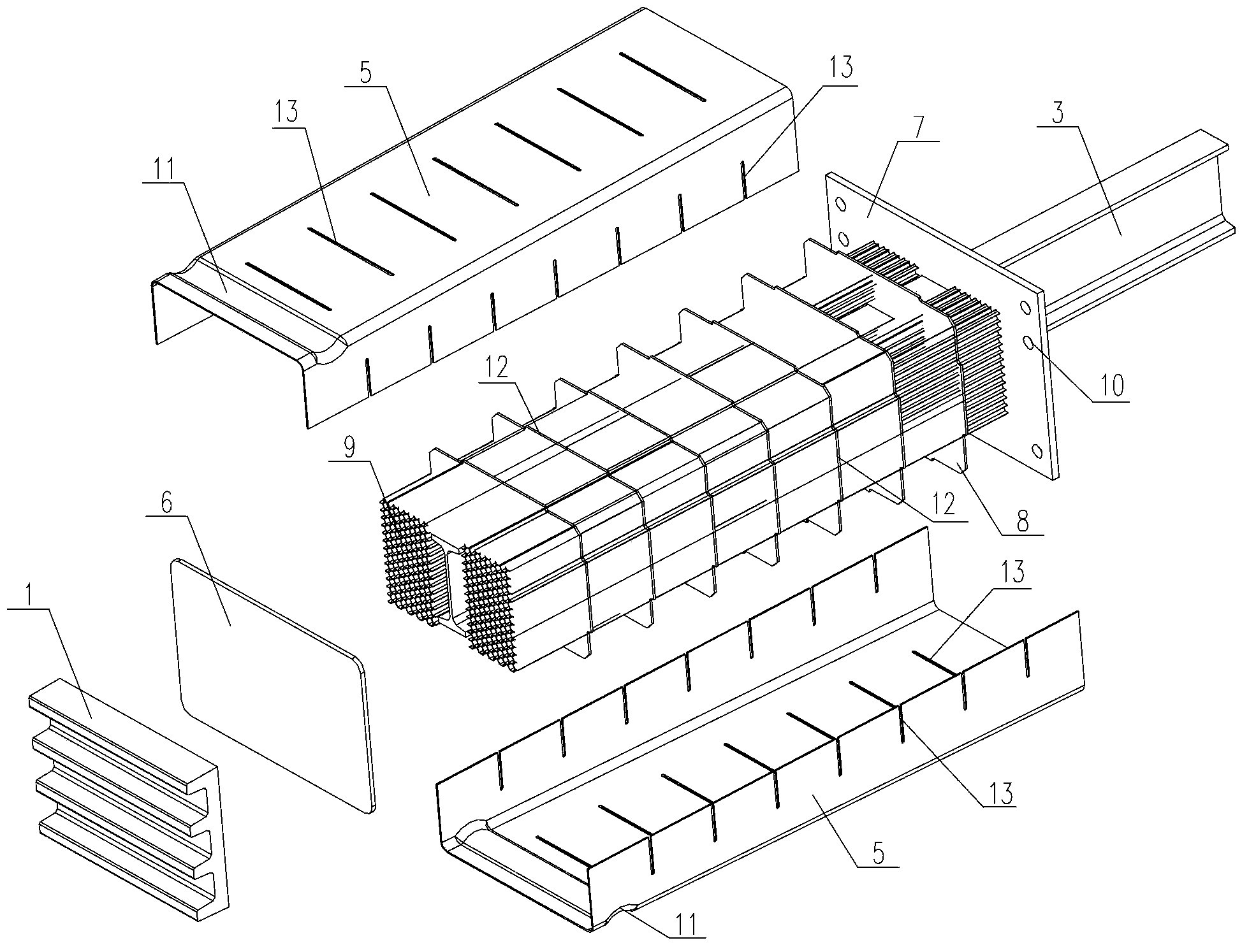
[0026] like figure 1 As shown, an anti-climbing energy-absorbing device for a rail vehicle according to the present invention is composed of an anti-climbing device 1 , an energy-absorbing body 2 and a guide rod 3 . The anti-climber 1 is located at the front end of the device, and the energy-absorbing body 2 is connected with the anti-climber 1 . After impact, the anti-climber 1 and the energy-absorbing body 2 move along the guide bar 3 .

[0027] like figure 2 and image 3 As shown, the anti-climbing device 1 is installed at the front end of the car body, and 3-5 anti-climbing teeth 4 alternately concave and convex are arranged laterally on the front end of the anti-climbing device 1. In this embodiment, 4 anti-climbing teeth 4 are arranged. ,, The anti-climbing device 1 adopts high-strength castings to ensure that it will not deform when i...


PUM


Abstract

The invention relates to an anti-creeping energy absorption device for a railway vehicle. The anti-creeping energy absorption device consists of an anti-creeping device, an energy absorption body and a guiding rod, wherein multiple anti-creeping teeth are transversely arranged on the front end face of the anti-creeping device, and the energy absorption body consists of an outer cover plate, a front installing plate, a rear installing plate, multiple rib plates and an energy absorption material. The front installing plate and the rear installing plate are respectively welded at two ends of the outer cover plate to form a box-shaped structure, the rib plates are parallelly arranged in the inner cavity of the box-shaped structure, and the energy absorption material is filled in the box-shaped structure. The front-end portion of the guiding rod and the anti-creeping device are fixed on the front installing plate, the guiding rod penetrates the inner cavity of the box-shaped structure and the rear installing plate and extends for a certain length, and the rear-end portion of the guiding rod is in sliding connection with a supporting plate. The anti-creeping energy absorption device can be prevented from being vertically unstable in the stress process, the energy absorption body performs energy absorption in a composite mode that the outer cover plate and the energy absorption material simultaneously deform plastically, the energy absorption effect is remarkable, and further vehicle body completion and person safety are ensured to the most extent.

Description

technical field [0001] The invention relates to an anti-climbing energy-absorbing device for rail vehicles, belonging to the technical field of rail vehicle manufacturing. Background technique [0002] Rail vehicle collision accidents are one of the most important causes of heavy passenger casualties. Therefore, how to improve the safety of rail vehicle operation and minimize the casualties of drivers, passengers and passengers in accidents has become a common concern. Especially now, with the rapid development of high-speed rail vehicles such as high-speed rail, the safety of vehicle operation has become more prominent. As an important part of vehicle design, collision safety issues have become a focus of high-speed rail vehicle installation. [0003] At present, domestic rail vehicles, in order to reduce the huge damage to the car body structure when the vehicles collide with each other, and to reduce casualties, safety protection devices such as anti-climbers are usually ...

Claims


Application Information

Patent Timeline
IPC IPC(8): B61F19/04
Inventor 钟元木刘龙玺梁海廷丁叁叁田爱琴田洪雷王军张在中
Owner CRRC QINGDAO SIFANG CO LTD
Learn More