Lighting control switch

A lighting control and switching technology, applied in lighting devices, light sources, electric light sources, etc., can solve the problems of narrow rotation range and difficult fine-tuning of light output.

Active Publication Date: 2014-05-07
PANASONIC INTELLECTUAL PROPERTY MANAGEMENT CO LTD
View PDF15 Cites 3 Cited by
  • Summary
  • Abstract
  • Description
  • Claims
  • Application Information

AI Technical Summary

Problems solved by technology

In short, there is a problem that it is difficult to perform fine adjustment of the light output due to the narrow rotation range available for adjustment of the light output of the lighting load.

Method used


Image

  • Lighting control switch
  • Lighting control switch
  • Lighting control switch

Examples


Embodiment Construction

[0038] The following description will be given of the lighting control switch of this embodiment with reference to the drawings.

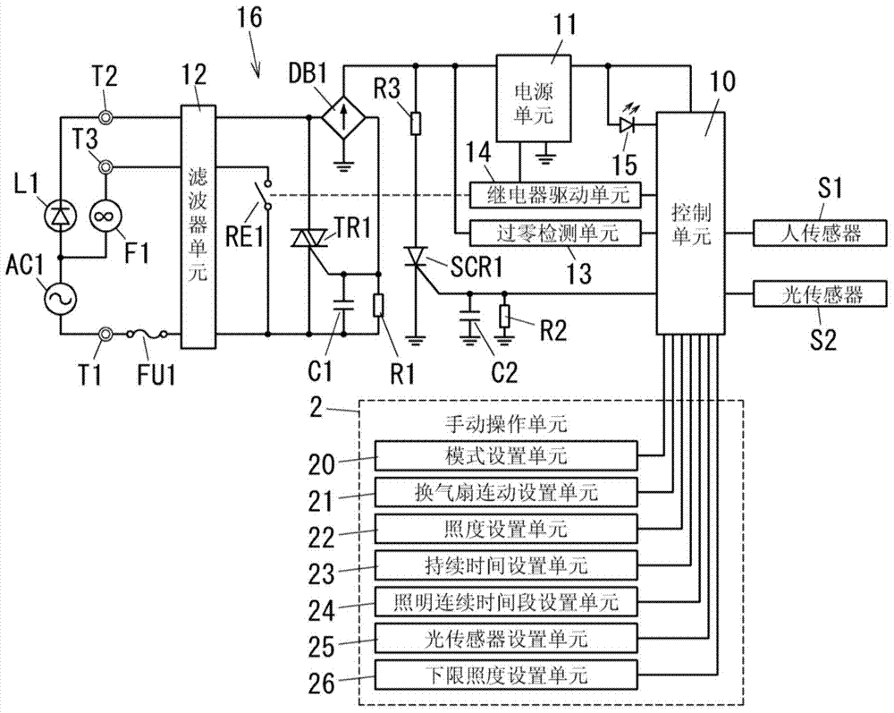
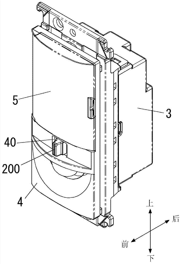
[0039] Such as figure 1 As shown in , the lighting control switch of this embodiment includes a control circuit (control unit) 10 for controlling the lighting load L1. In addition, the lighting control switch includes a manual operation circuit (manual operation unit) 2, a power supply circuit 16, a human sensor S1, and a light sensor S2. In addition, if image 3 and Figure 4 As shown in , the lighting control switch includes: a main body 3 for accommodating circuit blocks (control unit 10 , manual operation unit 2 , power supply circuit 16 , human sensor S1 and light sensor S2 ), a decorative cover 4 and a cover 5 .

[0040] The power supply circuit 16 is for supplying power to the lighting load L1 by using power from a predetermined power source (commercial AC power source AC1 in this embodiment).

[0041] The power supply circuit 16 include...


PUM


Abstract

The invention relates to a lighting control switch. The lighting control switch comprises a control unit used to control a lighting load, an illuminance setting unit of a manual operation component used to change operation amount in a preset range responding to manual operation of users, and a lower limit illuminance setting unit used to determine lower limit illuminance of the lighting load responding to manual input of users. The control unit is used to choose the illuminance according to operation amount and provide electricity corresponding to chosen illuminance for the lighting load. The control unit is used to choose the illuminance which is defined to be equal or higher than the lower limit illuminance as a regulated illuminance under the condition that the operation amount is lowest.

Description

technical field [0001] The present invention relates to a lighting control switch and in particular, to a lighting control switch for controlling power supplied to a lighting load. Background technique [0002] In the past, there has been proposed a lighting control switch installed in a corridor or a staircase and used to turn on and off a lighting load such as a corridor light or a stair light. Furthermore, there has been proposed a lighting control switch that turns on and off a lighting load installed in a bathroom and enables timer control of other loads such as a ventilation fan. This lighting control switch is disclosed in, for example, Document 1 (JP2008-4520A). [0003] The lighting control switch disclosed in Document 1 is provided on the front of the main body with a push operation unit for performing on / off operation of the lighting load, and a dimming time for setting a dimming time period for dimming the lighting load in a day segment setting unit. [0004] ...

Claims


Application Information

Patent Timeline
Patent Type & Authority Applications(China)
IPC IPC(8): H05B37/02
Inventor 上原健太郎平田聪松浦修次
Owner PANASONIC INTELLECTUAL PROPERTY MANAGEMENT CO LTD
Why Eureka
Try Eureka