Luminous intensity detection standard bulb

A luminous intensity detection and standard technology, applied in the direction of the shell/tube shell of the luminous body, the fixing part/support of the luminous body, etc., can solve the problems of difficulty in obtaining stable luminous intensity value, blackening of the surface of the bulb, and increasing production costs. , to achieve the effect of improving the service life, reducing the area and not easy to sag

Inactive Publication Date: 2014-05-07
詹云翔
View PDF5 Cites 0 Cited by
  • Summary
  • Abstract
  • Description
  • Claims
  • Application Information

AI Technical Summary

Problems solved by technology

At present, typical standard lamps for luminous intensity detection are generally only composed of bulbs and lamp holders, and stray light has a greater impact, and it is difficult to obtain stable and uniform light intensity values. Some standard lamps for luminous intensity detection use An overly complex structure increases production costs, and long-term use of filament oxidation will cause the surface of the bulb to blacken and affect the quality of light

Method used


Image

  • Luminous intensity detection standard bulb
  • Luminous intensity detection standard bulb
  • Luminous intensity detection standard bulb

Examples


Embodiment Construction

[0012] Below in conjunction with accompanying drawing and specific embodiment the present invention is described in further detail:

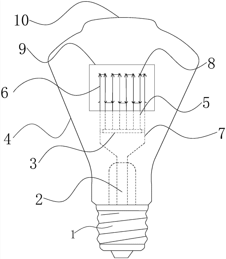
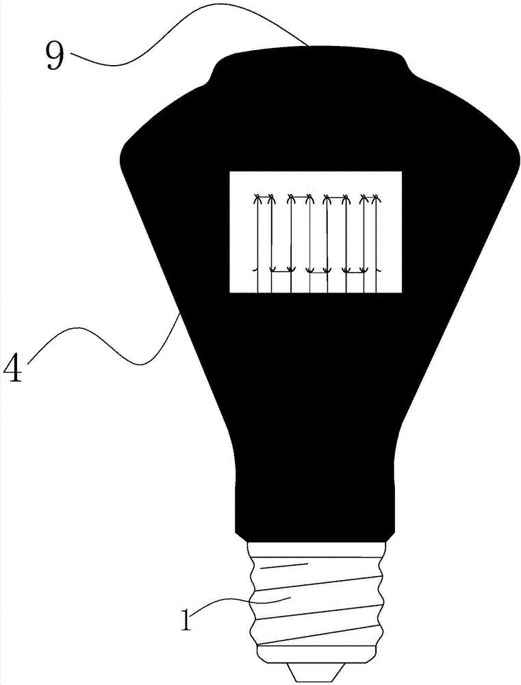
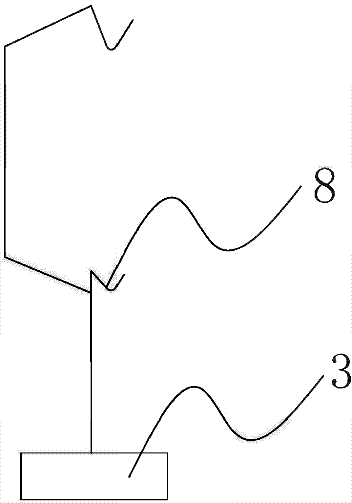
[0013] Such as figure 1 , figure 2 , image 3 with Figure 4 A standard light bulb for luminous intensity detection shown includes a lamp cap 1, a glass bulb 4, a stem 2 and a filament 6 are arranged inside the bulb 4, two guide wires 7 are drawn out of the stem 2, and the filament 6 The two ends are respectively connected with two guide wires 7. When the lamp cap 1 is on the bottom and the glass bulb 4 is on the top, the lamp as a whole is in the shape of an inverted cone or a rounded table, and the upper end surface of the glass bulb 4 is an arc surface; and the arc The center of the surface is provided with an arched protrusion 10, which accounts for 1 / 2-2 / 3 of the entire arc surface, and the height of the arched protrusion 10 is 3-8cm, and the inner wall of the glass bulb 4 Blackened, only a rectangular or square light-transmitting wind...


PUM

PropertyMeasurementUnit
Heightaaaaaaaaaa
Lengthaaaaaaaaaa
Widthaaaaaaaaaa

Abstract

The invention relates to a luminous intensity detection standard bulb. The luminous intensity detection standard bulb comprises a lamp holder and a glass casing. The glass casing is internally provided with a core column and a filament. The glass casing is inverted-conical shaped and is provided with an upper surface in the shape of an arc surface; the center of the arc surface is provided with an arc projection; the arc projection accounts for 1 / 2 to 2 / 3 of the whole arc surface; the inner wall of the glass casing is blackened; the glass casing right in front of the plane where the filament is located is provided with only a rectangular or square light transmission window; a fixation base is connected between two leads; the fixation base is provided with a plurality of molybdenum wire hook groups; each molybdenum wire hook group comprises two molybdenum wire hooks, i.e., a higher molybdenum wire hook and a lower molybdenum wire hook; the hook portions of the two molybdenum wire hooks are at the same vertical line; the filament successively passes through the hook portion at the top of each molybdenum wire hook from the left to the right according to a square wave shape; and the filament is disposed at the same plane. The luminous intensity detection standard bulb provided by the invention enables the adjustment of the filament to be simpler, and the glass casing is provided with the arc projection to concentrate the blackening phenomenon of the glass casing at the top portion so that the deposition area is concentrated, the area is reduced, and the service life of a bulb is improved.

Description

technical field [0001] The invention relates to a lamp, in particular to a standard bulb for luminous intensity detection. Background technique [0002] The standard lamp for luminous intensity detection is used to reflect and transmit the value of the luminous intensity unit (candela cd), and is an important standard instrument in the measurement of light radiation. Standard lamps for luminous intensity testing are generally made of incandescent lamps or tungsten halogen lamps. In order to make the filament the only illuminant of the standard lamp for luminous intensity testing, stray light from glass bulbs and other filament supports should be minimized. At present, typical standard lamps for luminous intensity detection are generally only composed of bulbs and lamp holders, and stray light has a greater impact, and it is difficult to obtain stable and uniform light intensity values. Some standard lamps for luminous intensity detection use An overly complex structure incr...

Claims


Application Information

Patent Timeline
IPC IPC(8): H01K1/28H01K1/32H01K1/18
Inventor 詹云翔
Owner 詹云翔
Why Eureka
Try Eureka