Optical fiber unit box and optical fiber unit box wiring method

A wiring method and unit box technology, applied in the direction of fiber mechanical structure, etc., can solve the problems of influence interference, easy operation errors, inconvenient operation, etc., to achieve the effect of clear wiring, avoiding adverse effects, and capacity expansion

Active Publication Date: 2014-05-07
SHENZHEN EPLU SCI TECH
View PDF5 Cites 9 Cited by
  • Summary
  • Abstract
  • Description
  • Claims
  • Application Information

AI Technical Summary

Problems solved by technology

The wide application of optical fibers with small curvature radius provides convenience for increasing the capacity of the optical fiber unit box, but at the same time as the capacity of the optical fiber unit box increases, the number of optical fiber cables and jumper fibers increases greatly, resulting in denser and more complex wiring and routing. Inconvenience to the operation
The existing optical fiber unit box is generally operated on one side. The optical fiber operation surface of the optical cable and the fiber jumper operation surface are all concentrated in the front of the optical fiber unit box, sharing one operation surface makes it easy to interfere with each other during operation, and the operation is prone to errors.
The limitation of the operation surface also limits the capacity of the optical fiber unit box, making it impossible to further expand the capacity
[0003] In the prior art, there is a lack of an optical fiber unit box and a wiring method for optical fiber unit boxes suitable for small curvature radius optical fibers that are simple in fiber jumper management, clear in wiring, and easy to operate, so that the fiber unit box can still be wired even in the case of a large capacity Clear, not easy to cause operational errors

Method used


Image

  • Optical fiber unit box and optical fiber unit box wiring method
  • Optical fiber unit box and optical fiber unit box wiring method
  • Optical fiber unit box and optical fiber unit box wiring method

Examples


Embodiment Construction

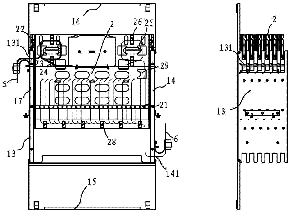
[0049] The existing optical fiber unit box is generally operated on one side. The optical fiber operation surface of the optical cable and the jumper fiber operation surface are all concentrated in the front of the optical fiber unit box. Sharing one operation surface makes it easy to interfere with each other during operation, and the operation is prone to errors. The limitation of the operation surface also limits the capacity of the optical fiber unit box, making it impossible to further expand the capacity. In order to solve the lack of a fiber jumper management in the prior art, which is simple in management, clear in wiring, and convenient in operation, it is suitable for the fiber unit box and the wiring method of the fiber unit box for optical fibers with small curvature radius, which can make the fiber unit box even in the case of large capacity. The wiring is still clear, and it is not easy to cause operational errors.

[0050] The optical fiber unit box of the prese...


PUM


Abstract

The invention discloses an optical fiber unit box and an optical fiber unit box wiring method. The box body is provided with two side plates which are oppositely arranged. At least one tray is arranged in the box body. Sliding mechanisms are arranged on both sides of the tray. The tray is slidably connected with two side plates through the sliding mechanisms and can be pulled back and forth relative to two side plates. An adapter installation plate is arranged on the tray, wherein an adapter is arranged on the adapter installation plate and front and back operation faces are formed on the tray. Each operation face is respectively a cable optical fiber operation face and a jumping fiber operation face. According to the optical fiber unit box and the optical fiber unit box wiring method, which are provided by the invention, operation is carried out on front and back operation faces by pulling the tray back and forth in front of and behind the box body; when large capacity and a lot of lines are in the optical fiber unit box, clear wiring can be ensured; operation confusion and mistakes are prevented; and the problems of chaotic wiring and inconvenient operation, which are caused by the fact that the cable optical fiber operation face and the jumping fiber operation face are concentrated to a direction of the optical fiber unit box for operation in the prior art, are solved.

Description

technical field [0001] The present invention relates to an optical fiber unit box and a wiring method for the optical fiber unit box, more specifically, to an optical fiber unit box that can be drawn back and forth and a wiring method for the optical fiber unit box. Background technique [0002] The usage scenarios of fiber optic unit boxes are generally installed in fiber optic distribution frames and IDC cabinets. With the continuous increase of the capacity of the equipment room, the fiber optic unit box is the main access terminal equipment of the fiber optic distribution frame, and its capacity also directly affects the equipment room. expansion. The wide application of optical fibers with small curvature radius provides convenience for increasing the capacity of the optical fiber unit box, but at the same time as the capacity of the optical fiber unit box increases, the number of optical fiber cables and jumper fibers increases greatly, resulting in denser and more com...

Claims


Application Information

Patent Timeline
Patent Type & Authority Applications(China)
IPC IPC(8): G02B6/44
Inventor 李中勋邵海波朱雪锋刘灿胜
Owner SHENZHEN EPLU SCI TECH
Why Eureka
Try Eureka